
Intel Xeon Processor and Intel E7500/E7501Chipset Compatible Platform Design Guide


Intel
®
Xeon™ Processor and Intel
®
E7500/E7501 Chipset Compatible Platform Design Guide 111
Hub Interface
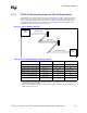
The values of R1, R2, R3, R4 and R5 must be rated at ± 1% tolerance. The selected resistor values
must also ensure that the reference voltage and reference swing voltage tolerance are maintained
over the input leakage specification. A 0.1 µF capacitor (C1 in Figure 7-8) should be placed within
0.5 inch of each resistor divider, and a 0.01 µF bypass capacitor (C2 in Figure 7-8) should be
placed within 0.25 inch of reference voltage pins. If the length of the trace from the voltage divider
to the pin is greater than 1 inch, place more than one 0.01 µF capacitor near the reference voltage
pin. The trace length from the voltage divider circuit to the HIREF and HUBREF pins must be no
longer than 3.5 inches.
Both the voltage reference and voltage swing reference signals should be routed at least 20 mils to
25 mils from all other signals.
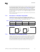
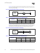
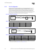
7.3.3 Hub Interface 1.5 Resistive Compensation
The hub interface uses a resistive compensation signal (RCOMP) to compensate buffer
characteristics for temperature, voltage, and process. The HIRCOMP resistor values are given in
Table 7-9. Figure 7-7 shows the RCOMP_x circuits. The length of the trace from the component to
the pull-up must be less than 1 inch and have a trace impedance of 50 Ω ± 10%.
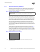
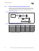
7.3.4 Hub Interface 1.5 Decoupling Guidelines
To improve I/O power delivery, use two 0.1 µF capacitors per each component (i.e., the ICH3-S
and MCH). These capacitors should be placed within 150 mils of each package, adjacent to the
rows that contain the hub interface. If the layout allows, wide metal fingers running on the VSS
side of the board should connect the VCC1_8/VCC1_2 side of the capacitors to the VCC1_8/
VCC1_2 power pins. Similarly, if layout allows, metal fingers running on the VCC1_8/VCC1_2
side of the board should connect the ground side of the capacitors to the VSS power pins.
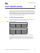
Table 7-9. Hub Interface 1.5 RCOMP Resistor Values
Component Trace Impedance RCOMP Resistor Value RCOMP Resistor Tied To
MCH 50 Ω ± 10% R1 = 24.9 Ω ± 1% VCC1_2
Intel
®
ICH3-S 50 Ω ± 10% R2 = 78.7 Ω ± 1% VCC1_8
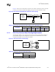
Figure 7-9. Hub Interface 1.5 RCOMP Circuits
R1
1.2 V
MCH
HIRCOMP
Intel
®
ICH3-S
HICOMP
R2
1.8 V
< 1.0" < 1.0"