
Intel Xeon Processor Multiprocessor Platform Design Guide

34
System Bus Routing
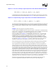
6.3.1 Processor I/O Decoupling Requirements
The primary objective of the processor I/O decoupling guidelines is to minimize the impact of
return path discontinuities. The processor power delivery guidelines help insure the processor I/O
has adequate power decoupling. The worst-case return path discontinuity anticipated is for systems
that use microstrip structures on the motherboard. The processors, from die to package pin, follow
a symmetric stripline configuration with V
CC_CPU
as one reference plane and V
SS
as the other
reference plane. If the motherboard uses symmetric stripline with V
CC_CPU
and V
SS
references,
then a discontinuity does not exist and additional decoupling is not necessary. If the motherboard
routing references only one reference plane (V
CC_CPU
or V
SS
), then a return path discontinuity
exists between the processor and the motherboard and decoupling capacitors are required.
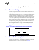
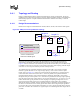
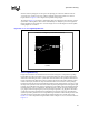
The decoupling recommendations for each processor is (shown in Figure 6-2):
• Four minimum, six preferred 0.1 µF capacitors with each processor, distributed evenly over
the system bus data signals
• Three minimum, four preferred 0.1 µF capacitors with each processor distributed evenly over
the system bus address and Common Clock signals
• All capacitors placed as close to the processor as keep-out zones allow
Figure 6-2. System Bus I/O Decoupling Guidelines for the Processor
Address and
Cntrl Field
Data Field
4-6 0.1[ uF ] with
603 body over the
data signals and as
close to the CPU
package as
possible
4-6 0.1[ uF ] with
603 body over the
data signals and as
close to the Processor
package as
possible
3-4 0.1[ uF ] with 603
body over the address
and cntrl signals and
as close to the chipset
package as possible
3-4 0.1[uF ] with 603
body over the address
and cntrl signals and
as close to the Processor
package as possible
Cavity under
Processor