
Intel Xeon Processor Multiprocessor Platform Design Guide


119
Design Checklist
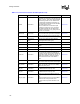
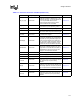
Processor Pin Signal Type Pin Connection Section No.
SM_TS_A[1:0]
1
Power/Other
Pull-up to VCC_SMBus with < 1 k
Ω resistors to
set bit high. Pull-down to VSS through < 1 k
Ω
resistors to set bit low. Use these address bits
to set a unique SMBus address for the
processor thermal sensing device. See the
processor datasheet for more details.
Section 6.4.2
SM_VCC Power/Other
Must be connected to 3.3 V power supply and
should follow the power sequencing routine.
Section 6.4.2
SM_WP
1
Power/Other If used, drive with 3.3 V compatible logic. Section 6.4.2
SMI# Power/Other
Connect to chipset or translation logic. Pull-up
with a 300
Ω resistor at processor end of signal.
Section 6.4.2
STPCLK# Asynch GTL+
Connect to chipset. Pull-up with a 300
Ω resistor
at processor end of signal.
Section 6.4.2
TESTHI[6:0] Power/Other
1 k
Ω pull-up to VCC_CPU. If boundary scan is
not required, TESTHI[0:3] may be tied together
and pulled up to VCC_CPU with a single 1 k
Ω
resistor, and TESTHI[5:6] may be pulled up to
VCC_CPU with a single 1 k
Ω resistor. TESTHI4
must always be pulled up separately on each
processor. Do not connect between processors.
THERMTRIP# Power/Other
Use a 56
Ω ± 5% pull-up to V
CC
and connect to
external logic to disable processor VCC_CPU
supply within 0.5 seconds after the assertion of
THERMTRIP# to protect the processors from
damage in over-temperature situations.
Section 6.4.2
TRDY# Common Clock Connect to all system bus agents. Section 6.4.1
V
CCA
Power/Other Connect through appropriate discrete filter. Section 8.13
V
CCIOPLL
Power/Other Connect through appropriate discrete filter. Section 8.13
V
CCSENSE
Power/Other
Place via next to processor pad for
measurement of V
CC
. Do not connect to sense
logic. Utilize this pin for power delivery
validation.
Section 8.13
VID[4:0] Power/Other
Connect to on-board VRM. X-OR signals
together to ensure all processors operate at the
same voltage. Optional: Connect to comparison
logic to compare VID of all installed processors
Section 6.4.2
V
SSA
Power/Other Connect to V
CCA
and V
CCIOPLL
filter. Section 8.13
V
SSSENSE
Power/Other
Place via next to processor pad for
measurement of V
CC
/V
SS
. Do not connect to
sense logic. Utilize this pin for power delivery
validation.
Section 8.13
Table 11-1. Processor Connection Checklist (Sheet 5 of 5)