
Intel Xeon Processor Multiprocessor Platform Design Guide

118
Design Checklist
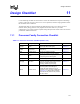
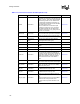
Processor Pin Signal Type Pin Connection Section No.
ODTEN Power/Other
Option 1 (preferred): Enable ODT (on-die
termination) on Processor 0 (end processor) by
pulling up to VCC_CPU with a resistor that falls
within the range of 50
Ω ± 20%. Disable ODT
for middle agent processors (Processors 1-3)
by pulling down to VSS with a resistor that falls
in the range of 50
Ω ± 20%.
Option 2: Enable ODT on Processor 0 (end
processor) by pulling up to VCC_CPU with a
1k
Ω resistor. Disable ODT for middle agent
processors (Processors 1-3) by pulling down to
VSS with a 1 k
Ω resistor.
Section 6.4.2
PROCHOT# Asynch GTL+
Connect to chipset GPIO or external logic. Pull-
up at both ends of the signal with 56
Ω resistors.
Section 6.4.2
PWRGOOD Asynch GTL+
300
Ω ± 5% pull-up to VCC. Connect to power
good circuitry of chipset and/or VRM.
Section 6.4.2
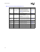
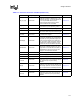
REQ[4:0]#
Source synch
AGTL+
Connect to all system bus agents. Balance
signal lengths within strobe group.
Section 6.4.1
Reserved Must remain unconnected.
RESET# Common Clock
Use a 50
Ω ± 5% pull-up to VCC. Connect to
chipset.
Section 6.4.1
RS[2:0]# Common Clock Connect to all system bus agents. Section 6.4.1
RSP# Common Clock Connect to all system bus agents. Section 6.4.1
SKTOCC# Power/Other
Connect to external logic as needed. Connect
pin of the second processor to BUSPARK on
the chipset. This pin maybe used to enable bus
paring feature if the chipset has an input pin. If
chipset uses software to enable bus parking,
Intel recommends the use of the software
option.
Section 6.4.2
SLP# Asynch GTL+
Connect to chipset or translation logic. Pull up
with a 300
Ω resistor at processor end of signal.
Section 6.4.2
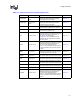
SM_ALERT#
1
Power/Other
Pull-up to SM_VCC and connect to SMBus
master. The number of devices on the SMBus
determines pull-up value.
Section 6.4.2
SM_CLK
1
Power/Other
Pull-up to SM_VCC. The number of devices on
the SMBus determines pull-up value.
Section 6.4.2
SM_DAT
1
Power/Other
Pull-up to SM_VCC. The number of devices on
the SMBus determines pull-up value.
Section 6.4.2
SM_EP_A[2:0]
1
Power/Other
Leave as no connect to set bit low. Pull up to
SM_VCC using a < 1 k
Ω resistor to set the bit
high.
Use these address bits to set a unique SMBus
address for the memory devices on the
processor. See the processor EMTS for more
details.
Section 6.4.2
Table 11-1. Processor Connection Checklist (Sheet 4 of 5)