
Intel Xeon Processor and Intel E7500/E7501Chipset Compatible Platform Design Guide


Intel
®
Xeon™ Processor and Intel
®
E7500/E7501 Chipset Compatible Platform Design Guide 245
Layout Checklist
Layout Checklist 14
All trace width and spacing recommendations are derived from a target impedance and crosstalk
sensitivity. This is based upon the stackup defined in Section 3.1. Any deviation from this stackup
must be simulated.
14.1 Processor Checklist
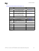
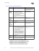
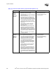
Table 14-1. Processor Layout Checklist (Sheet 1 of 2)
Checklist Items Recommendations Comments
A20M#
IGNNE#
INIT#
LINT0/INTR
LINT1/NMI
SMI#
SLP#
STPCLK#
• Trace impedance = 50
Ω ± 10%.
• Route traces using 5/10-mil spacing.
• Try to keep signals on the same layer for the
whole bus, but not at expense of AGTL+
Source Synchronous I/O.
• Maximum agent to agent length is 10". Place
pull-up resistor within 3" of Processor 1.
• Asynchronous GTL+ Input
Signals.
• Refer to Section 5.3.6.
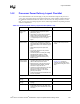
A[35:3]#
1
ADSTB[1:0]#
2
DSTBN[3:0]#
3
DSTBP[3:0]#
4
DBI3:0]#
D[63:0]#
5
REQ[4:0]#
6
• Trace impedance = 50 Ω ± 10%.
• Route Strobes 5/25 and others 5/15.
• Route all signals as groups, on the same
layer (do not change layer), and balance
within group ± 25 mils with respect to the
strobe.
• The distance from processor pin to
processor pin is between 3.0" and 7.0".
• The distance from processor pin to MCH pin
is between 3.0" and 6.5".
• Do not route a stub to Processor 1.
• AGTL+ Source Synchronous I/O.
• Refer to Section 5.1.
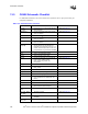
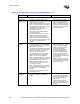
ADS#
AP[1:0]
BINIT#
BNR#
BR0#
DBSY#
DP[3:0]#
DRDY#
HIT#
HITM#
LOCK#
MCERR#
BPRI#
BR[3:0]#
DEFER#
RESET#
7
RS[2:0]#
RSP#
TRDY#
8
• Trace impedance = 50 Ω ± 10%.
• Route traces using 5/15-mil spacing.
• May change layers throughout the bus.
• Route traces with at least 50% of the trace
width directly over a reference plane.
• The distance from processor pin to
processor pin is between 3.0" and 7.0".
• The distance from processor pin to MCH pin
is between 3.0" and 6.5".
• Do not route a stub to Processor 1.
• Total bus length must not exceed 13.5".
• AGTL+ Common Clock Signals.
• Refer to Section 5.2.
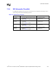
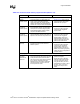
BCLK[1:0] • BCLKs to all processors should be length
matched, and the BCLK to the MCH should
be offset accordingly. See Table 4-3.
• System Bus Clock.
• Refer to Section 4.1.