
Intel Xeon Processor and Intel E7500/E7501Chipset Compatible Platform Design Guide

I/O Controller Hub 3 (Intel
®
ICH3-S)
152 Intel
®
Xeon™ Processor and Intel
®
E7500/E7501 Chipset Compatible Platform Design Guide
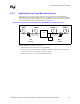
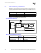
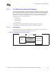
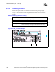
9.5.4 Calculating The Physical Segment Pull-Up Resistor
The following tables are provided as a reference for calculating the value of the pull-up resistor that
may be used for a physical bus segment. If any physical bus segment exceeds 400 pF, then a bus
bridge device like the Phillips PCA9515 must be used to separate the physical segment into two
segments that individually have a bus capacitance less than 400 pF.
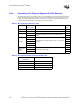
Table 9-1. Bus Capacitance Reference Chart
Device No. of Devices/
Trace Length
Capacitance Includes Cap
(pF)
Intel
®
ICH3-S 1 Pin Capacitance 12
CK408 1 Pin Capacitance 10
DIMMS 2 Pin Capacitance (10 pF) + 1 inch worth of trace capacitance
(2 pF/inch) per DIMM and 2 pF connector capacitance per
DIMM
28
3 42
PCI Slots
2
Each PCI add-in card is allowed up to 40 pF + 3 pF per each
connector
86
3 129
4 172
5 215
6 258
SMBus Trace
Length in
inches
≥ 24”
2 pF per inch of trace length
48
≥ 36” 72
≥ 48” 96
Table 9-2. Bus Capacitance/Pull-Up Resistor Relationship
Physical Bus Segment
Capacitance
Pull-Up Range (For Vcc = 3.3 V)
0 to 100 pF 8.2 kΩ to 1.2 kΩ
100 to 200 pF 4.7 kΩ to 1.2 kΩ
200 to 300 pF 3.3 kΩ to 1.2 kΩ
300 to 400 pF 2.2 kΩ to 1.2 kΩ