
Intel Xeon Processor and Intel E7500/E7501Chipset Compatible Platform Design Guide


Layout Checklist
256 Intel
®
Xeon™ Processor and Intel
®
E7500/E7501 Chipset Compatible Platform Design Guide
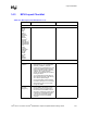
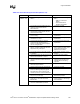
Power Decoupling
V_CPU_IO[2:0] • Use one 0.1 µF decoupling capacitor. Locate
within 100 mils of the ICH3-S processor
interface balls.
• Used to pull-up all processor I/F
signals.
VCC3_3 • Requires six 0.1 µF decoupling capacitors.
Distribute around the ICH3-S package sides
within 100 mils from the package balls:
– Top near AUX/PCI
– Left across the PCI and LPC
– Bottom near IDE.
VCCSus3_3 • Requires two 0.1 µF decoupling capacitors.
Place one capacitor on the top side within
200 mils of the USB center. Place other on
bottom side near the VCCSus3_3 supply.
VCC1_8 • Requires four 0.1 µF decoupling capacitors.
Locate two capacitors distributed local to the
hub interface; within 50 mils of the package
hub interface balls. Distribute remaining
capacitors on the left and bottom sides of the
package for core delivery.
VCCSus1_8 • Requires one 0.1 µF decoupling capacitor.
Locate within 200 mils of balls B23 and C23
of the ICH3-S.
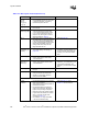
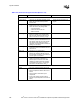
V5REF_Sus • Requires one 0.1 µF decoupling
capacitor.V5REF_Sus affects only 5-V
tolerance for USB OC[5:0]# balls, and can
be connected to VCCSus3_3 if 5 V tolerance
on these signal is not required.
V5REF • Requires one 0.1 µF decoupling capacitor.
V5REF is the reference voltage for 5-V
tolerant inputs in the ICH3-S. Tie to balls
V5REF[2:1]. V5REF must power up before
or simultaneous to VCC3_3. It must power
down after or simultaneous to VCC3_3.
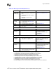
RTC
General
Guidelines
• RTC ball to crystal termination trace length
should be less than 1.0”.
• Minimize capacitance between RTCX1 and
RTCX2.
• Put ground plane underneath Crystal
components.
• Do not route switching signals under the
external components (unless on other side of
board).
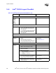
Table 14-4. Intel
®
ICH3-S Layout Checklist (Sheet 3 of 4)
Checklist Items Recommendations Comments