
Intel Xeon Processor and Intel E7500/E7501Chipset Compatible Platform Design Guide

Schematic Checklist
236 Intel
®
Xeon™ Processor and Intel
®
E7500/E7501 Chipset Compatible Platform Design Guide
V5REF_Sus • If USB is implemented in the platform,
V5REF_Sus must be connected to VSUS5.
• Use one 0.1 µF decoupling capacitor.
• Refer to Section 11.4.4.
V5REF • Requires one 0.1 µF decoupling capacitor. • Refer to Section 11.4.4.
Power Sequencing Requirements
V5REF_Sus and
VCCSus3_3
• V5REF_Sus must power up before or
simultaneous to VCCSus3_3. It must power
down after or simultaneous to VCCSus3_3.
(For most platforms this sequencing is not
an issues because VCCSus3_3 is derived
from V5SUS.)
• Refer to Figure 11-27 for an
example circuit schematic that
may be used to ensure the
proper V5REF sequencing.
V5REF and
VCC3_3
• V5REF must power up before or
simultaneous to VCC3_3. It must power
down after or simultaneous to VCC3_3.
• Refer to Section 11.4.2.
VCC3_3 and
VCC1_8
• The difference between VCC3_3 and
VCC1_8 must never be greater than 2.0 V.
• Refer to Section 11.4.1.
VCCSus3_3 and
VCCSus1_8
• The difference between VCCSus3_3 and
VCCSus1_8 must never be greater than
2.0 V.
• Refer to Section 11.4.1.
Power Management
THRM# • Connect to temperature Sensor.
• If not used: 8.2 k
Ω ± 5% pull-up to 3.3 V.
• Input to ICH3-S cannot float.
THRM# polarity bit defaults
THRM# to active low.
SLP_S3#
SLP_S5#
• No pull-up/down resistors needed. Signals
driven by ICH3-S.
• Signals driven by ICH3-S.
PWROK • This signal should be connected to power
monitoring logic and should go high no
sooner than 10 ms after both 3.3 V and
1.8 V have reached their nominal voltages.
• Use external weak pull-down.
• Refer to Section 9.6.8.
PWRBTN# • Connect to a momentary switch tied to
ground. No extra pull-up resistors.
• This signal has an integrated
pull-up of 18 k
Ω – 42 kΩ.
RI# • 8.2 k
Ω ± 5% pull-up to VCCSUS3_3. • If this signal is enabled as a
wake event, it is important to
keep this signal powered during
the power loss event. If this
signal goes low (active), when
power returns the RI_STS bit
will be set, and the system will
interpret that as a wake event.
RSMRST# • Can be tied to LAN_RST#.
• This signal should be connected to power
monitoring logic, and should go high no
sooner than 10 ms after both VCCSUS3_3
and VCCSUS1.8 have reached their
nominal voltages.
•10 k
Ω ± 5% pull-down to ground.
• Refer to Section 9.6.8.
SUS_STAT# • Do not connect.
• On remaining LPC bus devices, use 8.2 k
Ω
pull-up to 3.3 V.
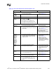
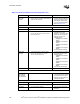
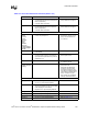
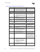
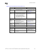
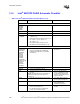
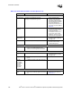
Table 13-3. Intel
®
ICH3-S Schematic Checklist (Sheet 5 of 6)
Checklist Items Recommendations Comments