
Intel Xeon Processor and Intel E7500/E7501Chipset Compatible Platform Design Guide

Platform Power Delivery Guidelines
204 Intel
®
Xeon™ Processor and Intel
®
E7500/E7501 Chipset Compatible Platform Design Guide
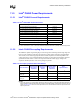
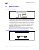
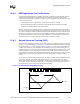
NOTE: The outlined area in the figure is the 3.3 V plane. Place at least five 0.1 µF capacitors in this area.
11.5.3 PCIRST# Implementation
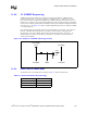
PCI-X requires a 100 ms delay from valid power (PWRGD) to reset deassertion (PCIRST#). The
system design must ensure this requirement is met.
The P64H2 reset must be deasserted within 60 ns of the MCH reset deassertion. Intel strongly
recommends customers measure this timing relationship on their boards. Failure to meet this
guideline may result in a system failing to boot.
11.5.4 Intel
®
P64H2 Power Sequencing Requirement
The 1.8 V voltage must be valid before the first CLK66 pulse is driven to the P64H2. This can be
guaranteed by gating the CK408 clocks using a power good signal from the 1.8 V regulator. When
the first CLK66 pulse is driven before 1.8 V is valid, the P64H2 PLL may fail to correctly lock.
The 1.8 V must drop with or before 3.3 V. This can be achieved by deriving 1.8 V from 3.3 V.
When 1.8 V drops after 3.3 V, a noise spike on PCIRST# approaches V
IH
minimum levels.
Figure 11-28. 3.3V PCI/PCI-X (VCC3_3) Capacitor Placement on Backside
0.1uF
AD24
AD1
A24
A1