
Intel Xeon Processor and Intel E7500/E7501Chipset Compatible Platform Design Guide


Memory Interface Routing Guidelines
100 Intel
®
Xeon™ Processor and Intel
®
E7500/E7501 Chipset Compatible Platform Design Guide
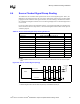
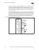
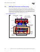
6.8 DDR Signal Termination and Decoupling
Place a 1.25 V termination plane on the top layer, just beyond (within 0.5 inch) the DIMM
connector furthest from the MCH on each channel, as shown in Figure 6-18. The VTERM island
must be at least 50-mils wide. Use this termination plane to terminate all DIMM signals, using one
Rtt resistor per signal. Decouple the VTERM plane using one 0.1 µF decoupling capacitor per two
termination resistors. Each decoupling capacitor must have at least two vias between the top layer
ground fill and the internal ground plane. In addition place one 100 µF Tantalum capacitor on each
end of the termination island for bulk decoupling. Refer to Figure 6-18.
Figure 6-18. DDR VTerm Plane
One 100 µF Tantalum
Capacitor at Each End
of Each Island
Furthest DIMM from MCH
1.25V Vterm Fill
One Rtt per signal
One 0.1 µF Decoupling
Capacitor per 2 Termination
Resistors or (2 Caps/Rpack)
0.5" max
Two Vias Per 1 Capacitor
to the Internal Ground
Plane
Ground Fill on
Top Layer
DIMM
DIMM
50 mils
minimum
50 mils
minimum
One 0.1 µF
decoupling
capacitor per 2
termination
resistors
Ground Fill
on Top Layer
1.25V
Vterm Fill
Two Vias Per 1
Capacitor to the
Internal Ground
Plane