
ITP700 Debug Port Design Guide


R
58 ITP700 Debug Port Design Guide
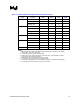
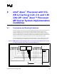
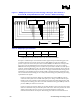
Table 33. BPM[5:0]# Figure Definitions
Parameter Min Nominal Max Notes
L
BPM
1 ns 1
NOTES:
1. BPM[5:0]# must be length matched to within 50 ps of themselves and RESET#.
2. Refer to the Platform Design Guide for BPM parameters between other components.
Clarification 1. The BPM[5:0]# and RESET# traces should be terminated to the processor VCC
voltage on both ends of the transmission line, similar to that of the system bus. For systems that
require on-die termination of the front-side bus, please note that the Intel Xeon processor with
512-KB L2 cache at 2.20, 2.0, and 1.80 GHz DP and Intel Xeon processor MP server systems do
not provide on-die termination of the BPM[5:0]# and RESET# signals. Consult individual chipset
documentation to assess if a chipset component should be connected to the BPM[5:0]# , RESET#,
or JTAG signals.
Clarification 2. The system clock of the Intel Xeon processor with 512-KB L2 cache at 2.20, 2.0,
and 1.80 GHz DP and Intel Xeon processor MP servers reference BCLK[1:0] where BCLK0 is the
rising edge for the beginning any transaction and BCLK1 is the falling edge. The ITP uses
BCLK[p/n] where BCLKp is the rising edge and BCLKn is the falling edge for the beginning of
any transaction. All routing Rules for the BCLK signals do not change.
Note: The BPM[5:0]# routing guidelines has changed. In the past, it was required to have BPM0# and
BPM2# tied as well as BPM1# and BPM3# tied together. This is no longer the case. It is now
recommended that all BPM[5:0]# signals be straight routed. For all legacy boards, the ITP will
still work with the previous routing configuration.