
Intel Xeon Processor and Intel E7500/E7501Chipset Compatible Platform Design Guide

Intel
®
Xeon™ Processor and Intel
®
E7500/E7501 Chipset Compatible Platform Design Guide 95
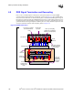
Memory Interface Routing Guidelines
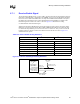
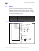
6.7.1 Receive Enable Signal
The E7500 chipset MCH uses the “receive enable” signal to determine the approximate round-trip
flight time (command flight + data flight) to the DIMMs. Two pins exist on the MCH to facilitate
the use of receive enable. RCVENOUT# is an output of the MCH and RCVENIN# is an input to
the MCH. The board designer must connect RCVENOUT# to RCVENIN#. The length of the
RCVEN# signal trace must be 15 inches ± 100 mils. Figure 6-12 illustrates the routing
recommendations of the RCVEN# signal.
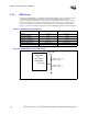
While the E7500 chipset MCH designs require this signal trace and a pull-up, the E7501 chipset
MCH only requires a pull-up resistor (Rtt) to DDR VTERM on RCVEN. If your board will only
use the E7501 chipset MCH, you do not need to route a 15-inch trace. Also, you do not need the
isolation resistor nor the trace between the isolation resistor and the No Connect. Figure 6-12
summarizes these options.
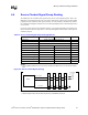
Table 6-10. Receive Enable Routing Guidelines
Parameter Intel
®
E7500 Chipset MCH Intel
®
E7501 Chipset MCH
Signal Group Receive Enable
Topology Feedback Loop Pull-up
Trace Impedance (Z
0
)50 Ω ± 10% 50 Ω ± 10%
Nominal Trace Width 5 mil 5 mil
Nominal Trace Spacing 15 mil 15 mil
Trace Length - MCH RCVENIN to Rtt < 1.0” N/A
Termination Resistor (Rtt) 47
Ω ± 2% 49.9 Ω ± 1%
Total Length 15" ± 100 mils No Requirement
Figure 6-12. Receive Enable Signal Routing Guidelines
Intel
®
E7500
chipset MCH
or
Intel
®
E7501
chipset MCH
DDR VTERM
(1.25 V)
E7500:RCVENIN
E7501: No Connect
E7500:RCVENOUT_x
E7501:RCVEN_x
RCVEN# Total Length:
15" ± 100 mils
E7500: 47 Ω ± 2%
E7501: 49.9 Ω ± 1%
E7500: 0 Ω
E7501: no pop