
Intel Xeon Processor and Intel E7500/E7501Chipset Compatible Platform Design Guide


System Bus Routing Guidelines
64 Intel
®
Xeon™ Processor and Intel
®
E7500/E7501 Chipset Compatible Platform Design Guide
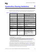
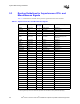
Refer to Table 5-2 for a summary of the dual-processor system bus routing recommendations. Use
this as a quick reference only. The following sections provide more detailed information for each
parameter. Intel strongly recommends simulation of all signals to ensure the design meets setup and
hold times.
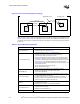
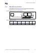
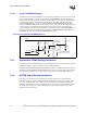
Figure 5-1. Dual Processor System Bus Topology
Processor 0
Processor 1
MCH
Motherboard Trace
3.0 – 7.0" 3.0 – 6.5"
Package Trace
Package
Traces
Table 5-2. System Bus Routing Summary
Parameter Platform Routing Guidelines
Trace Width/Spacing
• 5/15 mils.
• Serpentine ratio of 5:1. See Section 12.3.
2X and 4X Signal Group
• MCH-to-Processor: 3.0 inches– 6.5 inches pin-to-pin.
• Processor-to-Processor: 3.0 inches– 7.0 inches pin-to-pin.
• Total bus length must not exceed 13.5 inches.
• Balance trace lengths ± 25 mils with respect to the associated strobes
(see Table 5-4) between agents to compensate for the stub created by
the processor package. Use a Signal Integrity Adjustment Factor of 0.78.
See Section 12.6 for a detailed description of processor bus tuning.
• Route all signals within the same strobe group on the same layer for the
entire length of the bus.
• Never change layers on 2X and 4X signals.
• Never route over a plane split.
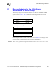
DSTBN[3:0]# / DSTBP[3:0]#
and ADSTB[1:0]#
• Follow the same routing rules as the 2X and 4X Signal Group.
• Maintain a 25-mil spacing around each strobe signal.
• Do not route differentially.
Common Clock Signal
• Follow the same routing rules as the 2X and 4X Signal Group; however,
no length compensation is necessary.
• If a layer change must occur, use vias connecting the two reference
planes to provide a low impedance path for the return current. Vias
should be as close as possible to the signal via.
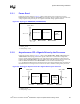
Topology
• Daisy chain with the chipset at one end of the system bus and
Processor 0 at the other.
• End processor must have on-die termination enabled.
Routing Requirements
• No motherboard contribution to stub length of middle processor
(35-mil max trace via to pad).
• Stripline, ground referenced only.
Motherboard Impedance • 50
Ω ± 10%