
Intel Xeon Processor and Intel E7500/E7501Chipset Compatible Platform Design Guide


Intel
®
82870P2 (P64H2)
128 Intel
®
Xeon™ Processor and Intel
®
E7500/E7501 Chipset Compatible Platform Design Guide
8.2.6.3 Debounced Hot-Plug Switch Input
The switch inputs (PxIRQ15 in this case—see Table 8-17) to the Hot-Plug controller do not require
any debouncing logic in this mode. This logic is contained within the P64H2. The POWERON
value for this input is determined by BIOS. However, it is recommended that BIOS define a logic 0
to represent that the slot can be powered on.
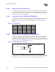
8.2.6.4 Comparator Circuit for PCIXCAP1/PCIXCAP2 Pins
A comparator circuit is required for properly decoding the PCI/PCI-X capability of the slot. Refer
to the PCI Local Bus Specification, Revision 2.2 for this circuit. For more information on the
reference circuit, refer to Section 8.2.7.9. The board designers could also use Table 8-16 as a
reference.
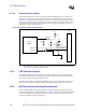
8.2.6.5 Tri-State Buffer or 2:1 Multiplexer for HPx_SLOT[2:0]
The HPx_SLOT [2:0] pins are pull-ups/pull-downs for determining the slot count and mode of
operation for the P64H2 Hot-Plug controller. The strapping value on these pins is latched on the
rising edge of PWROK. In single-slot parallel mode, these pins also function as the PCIXCAP1A,
PCIXCAP2A, and PCIXCAP1B inputs to the controller. Logic must exist to preserve the slot count
value when the system is in reset (PWROK signal is low).
It is also possible to accomplish this strapping requirement using a 2:1 multiplexer. The PWROK
signal can be used to enable the tri-state buffer. The decision is left up to the individual designer on
which method to use. See Figure 8-15 for an example of the optional multiplexer circuit.
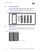
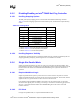
Table 8-16. Frequency Matrix
Frequency M66EN PCIXCAP1 PCIXCAP2 133EN
PCI 33 0XXX
PCI 66 100X
PCI-X 66 X 1 0 X
PCI-X 100 X 1 1 0
PCI-X 133 X 1 1 1
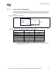
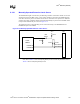
Figure 8-14. Tri-State Buffer Circuit Example
ENB
PCIXCAPx
Input
Decoded PCIXCAP
Signal from PCI SLOT
Enabled by PWROK#
1 kΩ