
Dual Intel Xeon Processor Voltage Regulator Down (VRD) Design Guidelines
Dual Intel
®
Xeon™ Processor Voltage Regulator Down (VRD) Guidelines
17
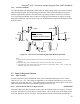
low-impedance (to ground) state whenever Vcc
is outside of the required range below and be in
the open state whenever Vcc is within its specified range, Section 2.1. On power up, the
PWRGD signal must remain in the low-impedance state until the output voltage has stabilized
within the required tolerance.
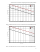
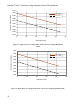
2.4.1 Power Good Threshold Voltages
The minimum voltage at which PWRGD is asserted should be the minimum Vcc specified in
Section 2.1.2, minus margin to prevent false de-assertion, but at least 95% of (VID minus
125mV).
The maximum voltage at which PWRGD is asserted should be the VID set-point voltage, plus
margin to prevent false de-assertion, but must be no greater than (VID plus 250 mV).
2.4.2 Power Good Operation
This PWRGD should be capable of sinking up to 4mA, while maintaining a voltage of 0.4V or
lower. When the output is in the open state it should be capable of withstanding up to 5.5V.
Latch-up or damage cannot occur if the pull-up voltage on the system board is present with no
+12V input present.
VRD Power Good should remain low if the VRD is disabled by the Output Enable pin.
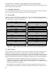
2.5 Intel Xeon Processor with 512-KB L2 Cache Power Sequencing
The Intel Xeon processor with 512-KB L2 cache’s and Low Voltage Intel Xeon processor’s VID
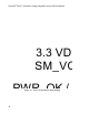
outputs use an active driver (Section 2.3.2). A 3.3-volt source connected to the processor’s
SM_VCC pins supplies the VID output devices. As shown in Figure 11, the VID outputs will be
valid within 10 milliseconds after the 3.3-volt supply reaches 95% of its nominal value. The
system power supply should generate PWR_OK no less than 100 milliseconds after all of its
outputs reach their respective 95% values. PWR_OK may be used to enable the VRD output.
For example, a supply adhering to ATX12V design guidelines meets this requirement. The
VRD’s PWRGD output may be used to generate the PWRGOOD input to the processor.
PWR_OK should be de-asserted when any output of the supply falls below 95% of its nominal
value (also consistent with ATX12V). It is important to maintain SM_VCC anytime the output
of the VRM is enabled. Driving The VRD’s OUTEN control input with the PWR_OK signal
will ensure correct sequencing at both power up and power down.