
Intel Xeon Processor Multiprocessor Platform Design Guide

69
Processor Power Distribution Guidelines
8.8.2 Sheet Inductance/Resistance and Emission Effects of
Power Plane
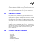
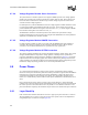
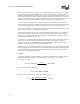
The imperfections of the power planes themselves may introduce unwanted resistance and
inductance into the power distribution system. Assuming layer thickness is smaller than skin depth,
the metal layer resistance can be calculated as:
Where ρ is the copper resistivity (ρ = 0.667 mΩ-mil), l, w, and t are the length, width and thickness
of the metal layer, respectively.
The loop inductance can be calculated as:
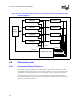
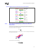
Figure 8-2. Suggested Twelve Layer Stack-Up for Four Processor Systems
Pwr plane
Layer 9
Signal
Layer 11 (1.5 oz.)
Gnd plane
Pwr plane
Layer 7
Signal
Layer 10 (1 oz.)
Layer 8 (1 oz.)
Gnd plane
Layer 6 (1 oz.)
Pwr plane
Layer 5 (1 oz.)
Layer 4
Signal
Gnd plane
Layer 3 (1 oz.)
Layer 2
Signal
Pwr plane
Layer 1 (1 oz.)
Gnd plane
Layer 0 (1.5 oz.)
R
l
wt
=⋅
⋅
ρ
w
l
h
t
L
lh
wN
=⋅
⋅
⋅−
319
1
.
()
pH
mil