
Intel Xeon Processor and Intel E7500/E7501Chipset Compatible Platform Design Guide

Schematic Checklist
230 Intel
®
Xeon™ Processor and Intel
®
E7500/E7501 Chipset Compatible Platform Design Guide
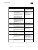
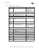
DDRCVOL_x
DDRCVOH_x
DDRCVO_x
• Connect as shown in Figure 6-17.•Refer to Section 6.7.4.
• DDRCVOL_x and
DDRCVOH_x are on the
E7500 chipset MCH and
DDRCVO_x is on the E7501
chipset MCH.
Hub Interface A
HI[11:0]
HI_STBF
11
HI_STBS
11
• Connect to ICH3-S.
•Must
not have pull-up, pull-down, or series
resistors.
• Refer to Section 7.3.1.
HIRCOMP_A • 24.9
Ω ± 1% pull-up to VCC1_2 • Refer to Section 7.3.3.
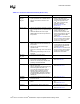
Hub Interface B, C, D
HI[18:0]
HI[21:20]
PSTRBF
PSTRBS
PUSTRBF
PUSTRBS
• Connect to P64H2.
•Must
not have pull-up, pull-down, or series
resistors.
• Refer to Section 7.2.1.
HIRCOMP_B
HIRCOMP_C
HIRCOMP_D
• 24.9
Ω ± 1% pull-up to VCC1_2 • Refer to Section 7.2.3.
Unused 16 bit
interfaces
• All data, strobe, HISWNG_x, and HIRCOMP_x
signals can be left as no connect.
• HIVREF_[D:B] must be connected to ground.
• The MCH has integration
detection logic that detects
unpopulated 16-bit interfaces
without external pull-ups and
pull-downs.
• Refer to Section 7.2.5.
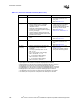
Clocks, Reset, Miscellaneous Signals
HCLKINP
HLCKINN
• Connect to CK408 through a 33 Ω ± 1% series
resistor with a 49.9
Ω ± 1% pull-down resistor to
ground.
• Refer to Section 4.1.
CLK66 • Connect to CK408 66BUF pin using a 43
Ω
± 5% series resistor.
• Refer to Section 4.2.
RSTIN# • Connect to PCIRST# output of the ICH3-S.
Miscellaneous Signals
XORMODE# • 4.7 kΩ ± 5% pull-up to 3.3 V. • Required for normal
operation.
Reserved
(Ball B30)
•4.7 k
Ω ± 5% pull-up to 3.3 V. • Required for normal
operation.
Reserved
(Ball D29)
•1 k
Ω ± 5% pull-down to Ground. • Required for normal
operation.
HXRCOMP
HYRCOMP
• Tie each COMP pin to a 25
Ω ± 1% pull-down to
ground.
• Refer to Section 5.3.3.
Table 13-2. MCH Schematic Checklist (Sheet 2 of 3)
Checklist Items Recommendations Comments