
Intel Xeon Processor and Intel E7500/E7501Chipset Compatible Platform Design Guide


Layout Checklist
254 Intel
®
Xeon™ Processor and Intel
®
E7500/E7501 Chipset Compatible Platform Design Guide
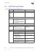
14.4 Intel
®
ICH3-S Layout Checklist
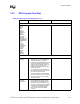
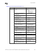
Table 14-4. Intel
®
ICH3-S Layout Checklist (Sheet 1 of 4)
Checklist Items Recommendations Comments
Processor Signals
A20M#
CPUSLP#
FERR#
IGNNE#
INIT#
LINT[1:0]
SMI#
STPCLK#
• See processor section of this checklist.
FWH Interface
Decoupling • 0.1 µF capacitors should be placed between
the VCC supply balls and the VSS ground
balls, and no less than 390 mils from the
VCC supply balls.
• 4.7 µF capacitors should be placed between
the VCC supply balls and the VSS ground
balls, and no less than 390 mils from the
VCC supply balls.
Hub Interface - See MCH section
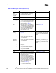
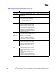
IDE Checklist
General
Guidelines
• Traces are routed 5-mil wide with 7-mil
spacing.
• Max trace length is 8 inches long.
• The maximum length difference between the
longest and shortest trace length is 0.5 inch.
• Refer to ATA ATAPI-4
specification.
• Refer to Section 9.1.3.
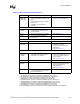
LAN Interface
General
Guidelines
• Traces: 5 mils wide, 10-mil spacing. • Refer to Section 9.7.
• LAN Max Trace Length Intel
®
ICH3-S to
CNR: L = 3" to 9" (0.5" to 3" on card).
• To meet timing requirements.
• Stubs due to R-pak CNR/LOM stuffing option
should not be present.
• To minimize inductance.
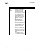
• Maximum Trace Lengths:
– ICH3-S to 82562EH: L = 4.5" to 10"
– 82562ET: L = 3.5" to 10"
– 82562EM: L = 3.5" to 10".
• To meet timing requirements.
• Maximum mismatch between the length of a
clock trace and the length of any data trace
is 0.5" (clock must be the longest trace).
• To meet timing and signal quality
requirements.
• Maintain constant symmetry and spacing
between the traces within a differential pair
out of the LAN phy.
• To meet timing and signal quality
requirements.