
Intel Xeon Processor and Intel E7500/E7501Chipset Compatible Platform Design Guide


Intel
®
Xeon™ Processor and Intel
®
E7500/E7501 Chipset Compatible Platform Design Guide 211
High-Speed Design Concerns
Differential clocking can also reduce the amount of noise coupled to other traces, which improves
signal quality and reduces EMI. I/O signals are particularly important because they often leave the
system chassis (serial and parallel ports, keyboards, mouse, etc.), and radiate noise that has been
induced onto them. A single-ended clock's return path is usually a reference plane, which is shared
by other signals/traces. When noise is created on a single-ended clock, the noise will appear on the
reference plane and may be coupled to I/O traces. A differential clock's return path is the clock-bar
signal/trace, which is more isolated than the reference plane and minimizes potential I/O trace
coupling.
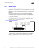
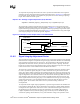
For best results, the trace lengths and routing of the clock lines must be closely matched, and
spacing between the two traces should be kept as small as possible. This minimizes loop area and
maximizes H-field cancellation. In addition, the real and parasitic terminations of each signal of a
differential pair should be the same. Also, the skew between the signal level transitions on the two
lines must be small compared to the rise time of the level transitions.
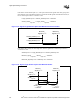
Placing ground traces on the outside of the differential pair may further reduce emissions.
Intermediate vias to ground may be needed to reduce the opportunity for re-radiation from the
ground traces themselves. Distance between vias should be less than ¼ of a wavelength of the fifth
harmonic of the processor core frequency.
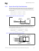
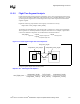
12.4.5 PCI Bus Clock Control
Experimental data has indicated a reduction in EMI may be possible by disabling the clocks to
unused (and therefore unterminated) PCI slots. CK408B, the clock chip that has been specified and
designed for this platform, supports individual control of the various PCI clocks. Designers have
the option to enable or disable individual PCI clocks depending upon their specific system
configuration requirements. Refer to the
CK408B Clock Synthesizer Design Guidelines for details
on how to configure the PCI clocks.
12.4.6 EMI Test Capabilities
FCC regulations in the United States specify the maximum test frequency for products with clocks
in excess of 1 GHz is five times the highest clock frequency or 40 GHz, which ever is lower. OEMs
are advised to inquire into the capabilities of their preferred EMC test lab to ensure they are able to
scan up to the required frequency range.
Processor performance and frequency double approximately every two years. With this in mind, it
is advisable to be prepared for the frequencies that will need to be scanned in the next few years.
Since the FCC rules ultimately require testing to 40 GHz, commercial test equipment has been
developed that is capable of making measurements to that frequency. Although it will be some time
before processors require testing at this frequency, it may be cheaper to upgrade to 40 GHz now,
rather than making several intermediate steps.
It is also possible to upgrade various parts at different times. The spectrum analyzer may be
upgraded to 40 GHz today with only the necessary antennas to support the initial processor
frequencies. As processor speed increases, the necessary antennas and cables can be purchased that
support testing to the higher levels.