
Intel Xeon Processor and Intel E7500/E7501Chipset Compatible Platform Design Guide

Intel
®
Xeon™ Processor and Intel
®
E7500/E7501 Chipset Compatible Platform Design Guide 181
Platform Power Delivery Guidelines
If available on the VRM, route the differential remote SENSE input signals
(VO-sen+ and VO-sen-) from both VRM connectors to the middle of the VCC_CPU plane. These
input signals allow the VRMs to sense output voltage and compensate for DC losses in the power
distribution path. The round trip trace resistance of these signals should not be greater than 1
Ω.
These voltage SENSE signals draw little current and should only have a minute voltage drop from
the remote sense connection to the VRM socket.
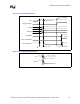
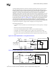
Route the VO-sen+ signal for each VRM to the same point on the VCC_CPU power plane in the
middle of and equidistant from both processors. Middle is defined as a point that provides the
shortest geometrical mid-point between the centers of the processor sockets. Route the VO-sen-
signal for each VRM to the same point at the corresponding X-Y location for the VO-sen+ route,
but on the VCC_VSS ground plane. See Figure 11-5 for an example of sense point locations for the
example VRM topology. The VO-sen+/VO-sen- signals should be routed directly from the VRM to
the remote sense point without exceeding 5 inches in trace length.
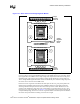
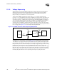
Figure 11-5. “Row” Pattern with Voltage Regulator Module
Voltage
Regulator
Remote
Sense
Voltage
Regulator
Module A
Voltage
Regulator
Module B
Proc A South Side Input
Proc A North Side Input
Proc B South Side Input
Proc B North Side Input