
Intel Xeon processor LV Thermal Design Guide

Dual-Core Intel
®
Xeon
®
processor LV and ULV
August 2006 Thermal Design Guide
311374-002 9
Package Information
2.0 Package Information
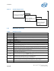
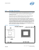
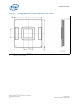
The component utilizes a 35 mm x 35 mm, micro FCPGA package (see Figure 2 through
Figure 8). The data is provided for reference only. Refer to the device’s most recent
datasheet for up-to-date data. In the event of conflict, the device’s datasheet
supersedes data shown.
The processor connects to the baseboard through a 479-pin surface mount, zero
insertion force (ZIF) socket. A description of the socket can be found in the Intel
®
Mobile Processor Micro-FCPGA Socket (mPGA479M) Design Guidelines.
The processor package has mechanical load limits that are specified in the processor
datasheet. These load limits should not be exceeded during heatsink installation,
removal, mechanical stress testing, or standard shipping conditions. The heatsink mass
can also add additional dynamic compressive load to the package during a mechanical
shock event. Amplification factors due to the impact force during shock must be taken
into account in dynamic load calculations. The total combination of dynamic and static
compressive load should not then exceed the processor datasheet compressive
dynamic load specification during a vertical shock. It is not recommended to use any
portion of the processor substrate as a mechanical reference or load bearing surface in
either static or dynamic compressive load conditions.
Figure 2. Package Dimensions (3D View)