
Intel Xeon Processor and Intel E7500/E7501Chipset Compatible Platform Design Guide

Intel
®
Xeon™ Processor and Intel
®
E7500/E7501 Chipset Compatible Platform Design Guide 79
System Bus Routing Guidelines
5.5.3 Thermal Sensor Selection
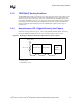
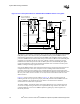
Figure 5-10 illustrates an example implementation where the same thermal sensor device used on
the Intel Xeon processor with 512-KB L2 cache (See Table 5-10 for details) is also placed on the
motherboard to provide equivalent thermal sensor operation between Intel Xeon processor with
512-KB L2 cache and Intel Xeon processor with 533 MHz system bus. Use of either of the thermal
sensor devices listed in Table 5-10 is not required as device selection should be based on the
features, operating requirements, or other factors defined by the platform.
NOTE: This list is provided for reference purposes only. It is not intended to be a complete list of available
components that can provide this function.
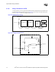
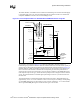
5.5.4 Thermal Sensor Layout and Routing Considerations
Because the motherboard thermal sensor device is measuring very small voltages from the
processor (Intel Xeon processor with 533 MHz system bus only) thermal diode, extreme care must
be taken to minimize the noise induced on the thermal sensor input pins. The following are
guidelines a motherboard designer can use to help ensure a clean thermal sensor implementation:
• Place the thermal sensor device as close to the processor socket as possible. Ideally, the
placement should be as close as possible to the THERMDA and THERMDC thermal diode
output pins to reduce the length of the processor thermal diode output signals to the thermal
sensor.
• Route the processor thermal diode output signals close together and in parallel. Intel strongly
recommends surrounding the signal pair with ground guard traces and adding component pad
sites close to the thermal sensor input to support a shunt capacitor between the THERMDA
and THERMDC signal traces.
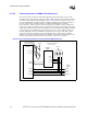
• Use wide traces and spacing to route the processor thermal diode output signals. This will
minimize induction and reduce the noise on these signals.
• Keep noisy sources such as clock generators and high-speed data and address buses away from
the thermal sensor and the processor thermal diode output signals to help minimize noise.
For more in-depth layout and routing considerations, please refer to documentation provided by
your thermal sensor device vendor.
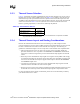
Table 5-10. Thermal Sensor Devices
Vendor Part Number
Philips Semiconductors NE1617A
Analog Devices, Inc. ADM1021A