
Intel Xeon Processor and Intel E7500/E7501Chipset Compatible Platform Design Guide

Platform Power Delivery Guidelines
184 Intel
®
Xeon™ Processor and Intel
®
E7500/E7501 Chipset Compatible Platform Design Guide
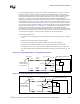
11.2.5.2 Loadline Selection Circuitry
Many OEMs require that a dual-processor VRD supplying an Intel processor’s common voltage
plane operate with either one or two processors installed on the board (i.e., the design must meet
the static and transient voltage characteristics of both the dual- and single-processor load lines).
Failure to adjust the voltage regulator’s loadline output based on the number of processors installed
will deteriorate the regulator’s ability to meet the processor’s static loadline requirements under
varying loads when one and two processors are installed. A solution is to adjust the load line for the
number of installed processors. OEMs that want jumper-free systems can do this with logic that
detects the presence of processors in each of the sockets, and selects resistor combinations to
produce the right slopes. For example: no processors (00) = disable VRD; one processor
(01 or 10) = single-processor load line; both processors (11) = dual-processor load line. Figure 11-9
shows an example of how to implement such circuitry.
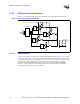
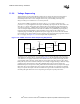
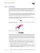
The theory of operation of the dual processor load line selection circuit is straightforward. If a
second processor (Processor 1) is not present, the base of Q3 will be pulled high. This causes Q3’s
collector to go to ground, turning off Q1 and Q2. The VCC_CPU voltage will then go through R2
(droop resistor) to pin 7 (FB) of the HIP6311A controller. The offset voltage comes from the +5 V
source through R1 into pin 7 of the controller. R3 and R4 will have no effect.
If a second processor is present, the base of Q3 will be pulled low and Q3’s collector will be high,
turning on Q1 and Q2. The droop resistor, R2, will now be paralleled by R4, providing the droop
required for a two-processor system. The offset resistor, R1, will be paralleled by R3 providing the
offset for a two-processor system.
Figure 11-9. Example Load Line Selection Circuit
Processor 1
SKTOCC#
HIP6311A
7
R1
R3
R2
R4
R6
R5
392 KΩ
340 KΩ
2.61 KΩ
1.96 KΩ
10 KΩ
10 KΩ
Q3
2N3904
Q2
BSS138
VCC_3.3
+5V
+5V
VCC_CPU
No CPU = HIGH
CPU = LOW
Q1
BSS138