
Intel Xeon Processor and Intel E7500/E7501Chipset Compatible Platform Design Guide


Platform Power Delivery Guidelines
176 Intel
®
Xeon™ Processor and Intel
®
E7500/E7501 Chipset Compatible Platform Design Guide
11.2 Processor Power Distribution Guidelines
11.2.1 Processor Power Requirements
This section describes the requirements for supplying power to an Intel Xeon processor. For
detailed electrical specifications, refer to the Intel
®
Xeon™ Processor Datasheet. The processor
allows the use of Auto HALT, Stop-Grant, and Sleep states to reduce power consumption by
stopping the clock to specific internal sections of the processor and the BCLK depending on each
particular state. This can create load-change transients as high as 450 A/µs on VCC_CPU at the
socket pins. Note that the processor can also cause load changes of this magnitude while executing
regular code. In this document, a load-change transient is a change from one current requirement
(averaged over many clocks) to another. In the future, the processor may require higher currents
and different voltages.
11.2.1.1 Multiple Voltages
“VCC_CPU” in this section refers to the processor core VCC, cache supply voltage, and Assisted
Gunning Transceiver Logic + (AGTL+) supply voltage. In the processor, the core and cache are on
the same silicon and are powered from the same power plane.
For the processor, VCCMAX = 1.500 V and SM_VCC_CPU = 3.3 V. The VCCA supplies power
to the processor core and on-die termination used for the AGTL+ bus.
VCCIOPLL, VCCA, and VSSA are the power supplies to the internal PLL. VCCIOPLL,VCCA
and VSSA must be connected to VCC_CPU through a discrete RLC filter as described in
Section 11.2.7. Refer to the Intel
®
Xeon™ Processor Datasheet for the pin locations of these
voltages.
11.2.1.2 Voltage Tolerance
Refer to the Intel
®
Xeon™ Processor Datasheet for voltage tolerance specifications. Failure to
meet these specifications on the low-end tolerance results in transistors slowing down and not
meeting timing specifications. Not meeting the specifications on the high-end tolerance can cause
damage or reduce the life of the processor.
The Intel Xeon processor specifications for VCC_CPU and ICC are not independent. The VID
definition is changed to absolute maximum VCC_CPU allowed. ICC_MAX is measured at
VCC_MAX.
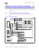
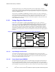
11.2.2 Power Delivery Layout Requirements
This section provides processor power delivery layout requirements that are common to both VR
Module (VRM) and VR Down (VRD) based designs. Designing a dual-processor system which
shares the same power plane requires careful consideration of how the VRM or VRD delivers
power to two processors that can vary their DC and AC loading requirements. Specific placement
recommendations for the VRM and VRD are detailed in Section 11.2.4 and Section 11.2.5
respectively. Note that the Voltage Regulator must be placed as close as possible to its processor,
on one of the two sides of the socket that has the greatest density of power and ground pins.
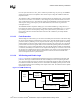
The maximum distance between each processor and its voltage regulator module or the output
inductors of an embedded Voltage Regulator should not be greater than 1.5 inches. To be more
specific, the distance between the facing edges of the Voltage Regulator connector and the socket
should be no more than 0.5 inch.