
ITP700 Debug Port Design Guide

R
20 ITP700 Debug Port Design Guide
is possible to terminate these signals using resistances equal to the characteristic impedance of the
motherboard using short (100 ps or less) stubs after the trace meets the ITP700 Flex surface mount
connector on the motherboard.
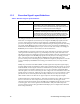
BPM[5:0]# lengths must still be matched on the motherboard to within 50 ps of one another and
with RESET# length D1 (see Figure 4 and Figure 5). Note that BPM5DR# is completely removed
form the ITP700 Flex design. Its functionality is integrated on the ITP700 Flex hardware. Systems
using the ITP700 Flex must only contain one load on the BPM[5:0]# signals and thus there can be
no BPM[5:0]# connections on the chipset.
Note: Note that BPM0# and BPM2# as well as BPM1# and BPM3# are no longer tied together at the
processor or the debug port. Instead they are routed directly through (eg BPM[5:0]# on the closest
agent routed directly to its corresponding pin BPM[5:0]# on the debug port or ITP700 Flex).
Since the BPM[5:0] Signals are terminated on the ITP700 Flex extension, the system bus
termination voltage (Vtt) must be connected to the debug port. Preferably the ITP700 Flex will be
located over the Vtt plane and pins 27 and 28 will be connected using short, wide traces to vias
connected to the Vtt plane. The maximum expected current on these two pins together is 1.5 mA.
If a plane is not available directly beneath the debug port connector, add a 0.1 µF ceramic cap
between Vtt and Ground within 0.1 inches of the Vtt pins of the debug port.
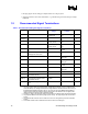
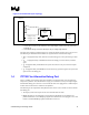
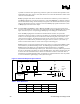
RESET# signal is a system bus signal and used in many places. The routing of the RESET# signal
will be defined by the Platform Design Guide. The following figure illustrates the layout of the
RESET# signal at the debug port. The information within the dotted box is a simplified
representation of the Platform Design Guide layout. This document will only define the parameters
D1, D2, D3, D4 and Ri at the debug port end of the RESET# line. Note that as the debug port will
be at one end of the transmission line, it will have a termination resistance of the same value as
that defined by the Platform Design Guide. Lengths D2, D3, and D4 should be as short as possible
so as not to disturb the signal integrity of this system bus signal.
Figure 3. ITP700 Flex Required Layout of Reset
CS uP
D1
D2
D3
Rt
Rt
Ri
D4
Vtt
Vtt
ITP700
Flex Reset
Signal
Platform Reset#
Signal
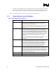
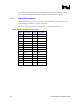
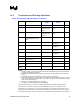
Table 7. Reset Definitions
Parameter Min Nominal Max Notes
D1 1 ns 1
D2, D3, D4 20 ps
Ri 150 Ω 5%