
Intel Xeon Processor Multiprocessor Platform Design Guide

99
Methodology for Determining Topology and Routing Guidelines
• Each timing component has an owner and revision date
• Rising and falling edges should be tracked separately
9.2 Simulation Methodology
This sections outlines the simulation methodology used to determine the topology and routing
guidelines.
9.2.1 Design Optimization
The layout for a high-speed bus design can be complex. High-frequency phenomena that
previously had second or third order effects on system level performance are becoming first order
as bus speeds continue to increase. It should be noted that for a high-speed bus, fixing a problem in
one area of the board might create another problem in a different area.
The design recommendations of this design guide have been written to provide enough detail to
allow a platform designer to go right into layout designs and only perform post-route simulations.
If any of the recommendations are not followed, then it is advisable to follow the complete
simulation process described below in order to accurately quantify your solution space.
9.2.2 Signal Categories and Topology Options
The first section of the bus design process is to determine all the signal categories contained within
the design. Categories should be defined by signal buffer type, timing requirements, and topology
similarities. The bus or component specification should provide help in this categorization.
Once signals have been categorized, all possible interconnect topologies for each signal group must
be determined. This requires significant collaboration with the layout engineer and will be the
direct result of a layout study. The optimum part placement and all possible interconnect solutions
should be determined. The layout study should produce a solution space that lists all possible
interconnect topology options including line lengths, widths and spacing. Extensive simulations
during the sensitivity analysis will be used to limit the solution space determined from the layout
study. This limited solution space becomes a final design solution that meets all timing and signal
quality specifications.
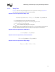
9.2.3 Sensitivity Analysis
A sensitivity analysis is used to determine the solution space for all aspects of the design. Every
parameter in the system bus should be varied in simulations. The performance metrics, such as
flight time, flight skew, and signal integrity are observed while each one of the variables is swept.
The performance as a function of each variable is compared to the timing and signal quality
specifications. As a result, limits are placed on each of the components. This produces a solution
space that places strict limits on the system variables such as trace lengths, spacing, impedance,
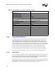
etc. The solution space will lead to design guidelines for the PCB and routing. Table 9-1 lists the
primary system variables that should be considered in the system bus sensitivity analysis. The
following table indicates the relative effect of each variable on system performance