
Intel Xeon Processor and Intel E7500/E7501Chipset Compatible Platform Design Guide


Layout Checklist
250 Intel
®
Xeon™ Processor and Intel
®
E7500/E7501 Chipset Compatible Platform Design Guide
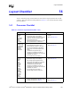
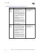
1.0 µF and
22.0 µF
decoupling
capacitor
quantity and
placement
• Use at least twenty, 22.0 µF ceramic
capacitors per processor socket.
• Use at least eight ,1.0 µF ceramic capacitors
per processor socket.
• Place one quarter of the caps on one side of
the processor socket, one quarter on the
other side, and half in the processor socket
cavity if using both sides of the motherboard.
• If using single-sided motherboards, place as
close to half the total quantity as possible,
and place the remaining caps on the outside
of the socket.
• Place capacitors as close to the power/
ground pins of the processor socket as
physically possible.
• Place capacitor vias within their pad. If this
technology is not feasible, then keep traces
between the pad and via as short and as
wide as feasible. Possibly one or both ends
of the capacitor may be connected directly to
the processor socket pin without the use of a
via
• Microstrip configurations require additional
decoupling capacitors.
• Refer to Section 11.2.9.1.
• Refer to the
Intel
®
Xeon™
Processor Datasheet
for the
processor pinout.
0.1 µF
decoupling
capacitor
quantity and
placement
• Distribute four minimum (six preferred)
0.1 µF capacitors evenly across the
VCC_CPU / ground pins that are located in
the portion of the processor socket pinout
where system bus data lines are located.
• Distribute three minimum (four preferred)
0.1 µF capacitors evenly across the
VCC_CPU / ground pins that are located in
the portion of the processor socket pinout
where address and common clock signals
are located.
• Place all capacitors as close to the power/
ground pins of the processor socket as
physically possible.
• Place capacitor vias within their pad. If this
technology is not feasible, then keep traces
between the pad and via as short and as
wide as feasible. Possibly one or both ends
of the capacitor may be connected directly to
the processor socket pin without the use of a
via.
• Refer to Section 11.2.9.1 for a
placement example.
• Refer to the
Intel
®
Xeon™
Processor Datasheet
for the
processor pinout.
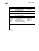
Table 14-2. Processor Power Delivery Layout Checklist (Sheet 4 of 4)
Checklist Items Recommendations Comments