
Intel Xeon Processor Multiprocessor Platform Design Guide

75
Processor Power Distribution Guidelines
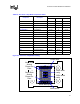
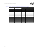
Table 8-2. Processor Lump Model Component Values
Component Description
Value
Resistance Inductance Capacitance
1206s North/South Five 22
µF MLCC 10 mΩ / 5 1.1 nH / 5 5 * 22 µF
1206s North/South Cavity Five 22
µF MLCC 10 mΩ / 5 1.1 nH / 5 5 * 22 µF
1206s int Interposer MLCC 833 µΩ 45 pH 120 µF
DIP Capacitors Package Capacitors 270
µΩ 2.35 pH 36 µF
Core capacitors Die Capacitance 146
µΩ 0 541 nF
L1 North Side Input 170 µΩ 23 nH -
L2 North Side Pin Field Input 150
µΩ 23 nH -
L3 North Side Cavity Input 120
µΩ 18 nH -
L4 Cavity 130
µΩ 20 nH -
L5 South Side Cavity Input 120
µΩ 18 nH -
L6 South Side Pin Field Input 150
µΩ 23 nH -
L7 South Side Input 170
µΩ 23 nH -
Lskt Socket Impedance 326
µΩ 24 pH -
Lint Interposer Impedance 125
µΩ 12 pH -
Lcore Package Impedance 25
µΩ 1 pH -
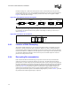
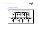
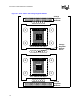
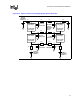
Figure 8-6. Processor Lump Model Drawing
South Side Input
North Side Input
1206s north
1206s south
1206s north
cavity
1206s south
cavity
North Side
Socket
Power Pin
Field
South Side
Socket
Power Pin
Field