
Intel Xeon Processor Multiprocessor Platform Design Guide

46
System Bus Routing
6.4.2.2 Topology 2: Asynchronous GTL+ Signals Driven by the Chipset;
A20M#, IGNNE#, INIT#, LINT[1:0], PWRGOOD, SLP#, SMI#, and
STPCLK#
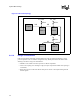
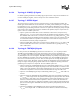
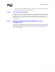
These signals should adhere to the following routing and layout recommendations. Figure 6-11
illustrates the recommended topology. When routing to middle agents connect in true daisy chain
topology. Do not create a stub to connect to the socket pins.
It may be desirable to isolate PWRGOOD for each VRM and processor pair in order to recognize
individual VRM failures.
6.4.2.3 Topology 3: VID[4:0]
The VID[4:0] signals for the Intel Xeon processor MP and Intel Xeon processor MP with up to
2-MB L3 cache on the 0.13 micron process should be routed to the VID[4:0] inputs on the voltage
regulator controller. The voltage regulator controller should provide internal pull-up resistors for
these signals. Refer to the VRM 9.1 DC-DC Converter Design Guidelines and the specification of
the voltage controller specific to your design for further details.
Since all processors must operate at the same V
CC
voltage, it is imperative to provide a way to
check the VID[4:0] signals to ensure a processor does not operate out of specification.
6.4.2.4 Topology 4: SMBus Signals
The SMBus signals provide access to the manageability features on the processor. The signaling
protocol adheres to the specification of the System Management Bus. Refer to the processor
datasheet for details on the processor SMBus implementation and addressing scheme.
The SM_ALERT#, SM_CLK, and SM_DAT signals should be connected to SMBus controller in
adherence to the System Management Bus Specification, rev 2.0. These signals can be connected to
other processors on the same SMBus.
The SM_EP_A[2:0] signals set the SMBus address for the memory device on the processor. These
signals need to be set at power up with a unique address per bus. They have an internal 10 kΩ pull
down. To pull a signal to a logic high level, connect to a 100 Ω resistor tied to SM_VCC.
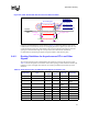
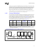
Trace Zo Trace Spacing L1 L2 L3 Rpu
50
Ω 10 mil 4–6” 1-12” 3” max 300 Ω ± 5%
Figure 6-11. Topology 2 for 4-Way Configuration
IOC
CPU1
CPU3 CPU4CPU2
Rpu
L1L1
L1 L2
L3
Vcc
CP
U