
Intel Xeon processor LV Thermal Design Guide

Dual-Core Intel
®
Xeon
®
processor LV and ULV
August 2006 Thermal Design Guide
311374-002 17
Mechanical Specifications
4.0 Mechanical Specifications
4.1 Package Mechanical Requirements
The package level requirement are detailed in Section 2.0 including the maximum
pressure allowed on the bare die package. More information may be available in the
Dual-Core Intel
®
Xeon
®
processor LV and ULV Datasheet.
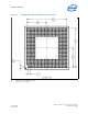
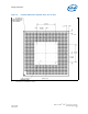
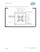
4.2 Package Keep-Out Zones Requirements
The heatsink should not touch the package in the areas shown in Figure 7. However,
the heatsink should include a means to prevent the heatsink from forming an electrical
short with the capacitors placed on the top side of the package. Suitable methods
include using electrically insulated gasket material at the base of the heatsink.
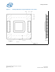
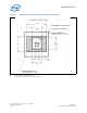
4.3 Board Level Keep-Out Zone Requirements
A general description of the keep-out zones and mounting hole pattern for the
reference thermal solutions are shown in Figure 9 and Figure 10. Detailed drawings for
the PCB keep-out zones are contained in Appendix B, “Mechanical Drawings”.
Components placed between the underside of the heatsink and motherboard cannot
exceed 4.75 mm in height when using heatsinks that extend beyond the socket
envelope shown in Figure 9.