
Intel Xeon Processor and Intel E7500/E7501Chipset Compatible Platform Design Guide

Intel
®
Xeon™ Processor and Intel
®
E7500/E7501 Chipset Compatible Platform Design Guide 43
Baseboard Requirements
3.4.4 Connectors
The SSI Spec requires that your baseboard have the following connectors: Main Power Connector,
+12 Volt Power Connector, Auxiliary Signal Connector, and cooling fan connectors. All of this
information is in the SSI Specification, but is presented here for convenience. This information
also meets the EPS12V Power Supply Design Guide Version 1.6. The Power Supply Design Guide
supercedes all documentation here.
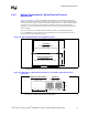
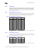
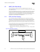
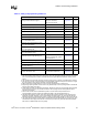
3.4.4.1 Entry SSI Main Power Connector
The baseboard must have a 24-pin Molex 44472 family connector or equivalent. The header must
have the pinout as enumerated in Table 3-3. The PWR OK signal has strict electrical requirements,
as documented in the SSI EEB Specification, Version 3.0, Section 5.3.1.5 (Power OK).
NOTE: This table is a copy of the SSI EEB Specification, Version 3.0, Table 3: Entry SSI Main Power Connector
Layout.
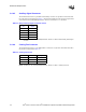
3.4.4.2 +12 Volt Power Connector
The baseboard must have an 8-pin Molex 44472 family connector or equivalent. The header must
have the pinout as enumerated in Table 3-4. The SSI Specification dictates that the +12V3 rail on
the motherboard must be separate from the +12V2 rail.
NOTE: This table is a copy of the SSI EEB Specification, Version 3.0, Table 4: Electronics-Bay +12 Volt Power
Connector Layout.
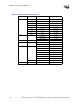
Table 3-3. Entry SSI Main Power Connector Pinout
Pin Signal Pin Signal
1 +3.3 VDC 13 +3.3 VDC
2 +3.3 VDC 14 -12 VDC
3COM 15COM
4 +5 VDC 16 PS ON
5COM 17COM
6+5 VDC 18 COM
7COM 19COM
8PWR OK 20 Rsvd
9 5 VSB 21 +5 VDC
10 +12V2 VDC 22 +5 VDC
11 +12V2 VDC 23 +5 VDC
12 +3.3 VDC 24 COM
Table 3-4. Entry SSI +12 Volt Power Connector Pinout
Pin Signal Pin Signal
1 COM 5 +12V1 VDC
2 COM 6 +12V1 VDC
3 COM 7 +12V1 VDC
4 COM 8 +12V1 VDC