
Intel Xeon Processor and Intel E7500/E7501Chipset Compatible Platform Design Guide


Intel
®
Xeon™ Processor and Intel
®
E7500/E7501 Chipset Compatible Platform Design Guide 33
Baseboard Requirements
Baseboard Requirements 3
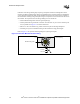
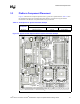
This chapter summarizes the stack-up used for all platform simulations, the placement of
components on the motherboard, and required features to be SSI compliant.
3.1 Platform Stack-Up
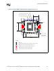
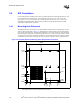
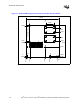
Figure 3-1 shows the recommended platform stack-up. All layers are 1 oz copper. The processor
requires 2 oz of copper to deliver power and 2 oz of copper to deliver ground.
Route signal layers as asymmetric stripline on layers 2, 4, 5, and 7. The signal layers must
reference ground on layer 3 or layer 6 only. Route signals on layers 4 and 5 orthogonally with
respect to routes on signal layers to reduce crosstalk between the layers.
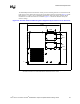
Intel strongly recommends that system designers use the stack-up shown in Figure 3-1 and
recommendations in Table 3-1 when designing their boards. Intel realizes numerous ways exist to
achieve these targeted impedance tolerances; contact your board vendor for these specifics. Intel
encourages platform designers to perform comprehensive simulation analysis to ensure all timing
specifications are met. This is particularly important if a design deviates from the design guidelines
provided.
Figure 3-1. 8 Layer, 50 Ω Board with 5-Mil Traces
Core 5.2 mil
Dielectric 9.6 mil
2.1 mil (0.5 oz +
1.0 oz plating)
Power
Dielectric
SignalSignal Signal
Power
Dielectric
SignalSignal Signal
Ground
Main Core
Dielectric
SignalSignal Signal
Core
Ground
Dielectric
SignalSignal Signal
Core
1.4 mil (1 oz)
Core 5.2 mil
Dielectric 4.3 mil
Core 14.0 mil
Dielectric 9.6 mil
Dielectric 4.3 mil
Layer 1
Layer 2
Layer 3
Layer 4
Layer 5
Layer 6
Layer 7
Layer 8
1.4 mil (1 oz)
1.4 mil (1 oz)
1.4 mil (1 oz)
1.4 mil (1 oz)
1.4 mil (1 oz)
2.1 mil (0.5 oz +
1.0 oz plating)