
Intel Xeon Processor and Intel E7500/E7501Chipset Compatible Platform Design Guide

Intel
®
Xeon™ Processor and Intel
®
E7500/E7501 Chipset Compatible Platform Design Guide 229
Schematic Checklist
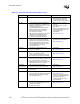
13.2 MCH Schematic Checklist
L
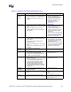
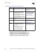
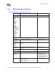
Table 13-2. MCH Schematic Checklist (Sheet 1 of 3)
Checklist Items Recommendations Comments
Host Interface
ADS#
AP[1:0]
BINIT#
BNR#
BPRI#
BREQ0#
1
CPURST#
2
DBI[3:0]#
DBSY#
DEFER#
DP[3:0]#
DRDY#
HA[35:3]#
3
HD[63:0]#
4
HADSTB[1:0]#
5
HDSTBN[3:0]#
6
HDSTBP[3:0]#
7
HIT#
HITM#
HLOCK#
HREQ[4:0]#
8
HTRDY#
9
RS[2:0]#
RSP#
XERR#
10
• See processor section of this checklist.
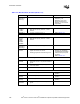
DDR Interfaces A and B / Connector
DQ_x[63:0]
CB_x[7:0]
DQS_x[17:0]
• Dependant upon configuration. • Refer to Section 6.2.
MA_x[12:0]
BA_x[1:0]
RAS_x#
CAS_x#
WE_x#
• Terminate these signals to DDR VTERM
(1.25 V).
• Refer to Section 6.4.
CS[7:0]_x# • Terminate these signals to DDR VTERM
(1.25 V).
• Refer to Section 6.5.
CMDCLK_x[3:0]
CMDCLK_x[3:0]#
• Connect directly to the corresponding DIMM. • Refer to Section 6.3.
CKE_x • Terminate to DDR VTERM (1.25 V). • Refer to Section 6.6.
RCVENIN_x#
RCVENOUT_x#
RCVEN_x
• Connect as shown in Figure 6-12. • Refer to Section 6.7.1.
• RCVENIN_x# and
RCVENOUT_x# are on the
Intel
®
E7500 chipset MCH
and RCVEN_x is on the Intel
®
E7501 chipset MCH.
DDRCOMP_x • For E7500 chipset MCH, 6.98
Ω ± 1% pull-up to
DDR VTERM (1.25 V).
• For E7501 chipset MCH, 24.9
Ω ± 1% pull-
down to Ground.
• Refer to Section 6.7.2.