
ITP700 Debug Port Design Guide


R
ITP700 Debug Port Design Guide
81
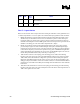
11 Appendix B – Buffering TCK
While Intel strongly recommends implementing TCK for the scan chain using TCK and a matched
star topology, there are situations that require buffers to be placed in the TCK path. Assure that the
buffers chosen to drive TCK will be able to operate in the voltage range appropriate to the target
TAP interfaces. There have been several successful buffer implementations using a 74VCX style
part such as a 74VCX 244. Manufacturer’s datasheets indicates this device will operate down to
1.65 V and will drive both high and low sides of the signal swing. GTL drivers will not work for
TCK buffers due to the fact that the TCK should be pulled-down to guarantee an idle low. Be
mindful of the edge rates of the outputs of the chosen buffer. Some TAP agents will be damaged
due to overshoot of high edge rate un-terminated signals.
FBI is provided on the debug port specifically as a source clock for a TCK buffer. FBI is
essentially the same signal as TCK on the debug port, but without the passive edge rate filtering
present on TCK. FBI must be lightly loaded. It is recommended that a single buffer be used for
each scan agent in the chain. If an extra buffer is available in the package, route FBI to this buffer
to create a spare copy of TCK to be used for FBO feedback. This net should be routed to FBO
with an electrical length equal to the matched length of the scan chain TCK nets plus the electrical
length of the BPM[5:0]# and RESET# signals from the nearest system bus agent to back to the
debug port.
It is important to verify timing analysis of the scan chain to ensure that there is adequate setup and
hold margins on TMS, TDI, and TDO for each scan chain agent as well as the debug port. It might
be necessary to route TMS through the buffer in order to guarantee timings for the scan chain.