
ITP700 Debug Port Design Guide


R
76 ITP700 Debug Port Design Guide
• The RESET# will only be necessary where a reset, unique and independent from the processor
node debug port, is required for devices in the I/O domain.
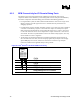
Note: Timing of debug port TAP signals (to and from the components) must be verified to meet the
setup and hold times after component timing, debug port timing, trace delays, and any intermediate
buffers are considered. Since the Event Bus signals are asynchronous, there is no requirement to
control BCLKP/BCLKN delays from clock source to debug port (as there are for the Processor
Node debug port). Please consult the appropriate Platform Design Guide for connectivity and
termination requirements for Event Bus signals.
9.2 The Miscellaneous Debug Port Guidelines
Some of the debug port signals are optional. They may require use or may be left unconnected,
depending on platform architecture. In particular:
• The DBA# signal will only be necessary if the target system requires selection between
alternate sources for control of the JTAG scan chains.
• The DBR# signal will only be necessary if there is a need to independently assert a local reset
to that sub-section of the system. Note that at least one DBR# should be implemented from
some debug port so that the ITP host can force a hardware reset of the platform.
• The FBI signal will only be necessary if there is a need to drive TCK via clock buffers to
devices in the local scan chain. TCK for the scan chain would normally be driven directly by
the debug port TCK output.
• The RESET# will only be necessary where a reset, unique and independent from the processor
node debug port, is required for devices on the miscellaneous debug port.
• The debug port BPM inputs/drive can be used to sense signals of various functionality, as
long as the signaling requirements for the ITP (as defined in the RS--Intel 870 Electrical,
Mechanical and Thermal Specification) are met.