
Intel Xeon Processor Multiprocessor Platform Design Guide


117
Design Checklist
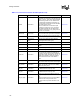
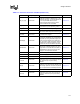
Processor Pin Signal Type Pin Connection Section No.
DSTBN[3:0]#
Source synch
AGTL+
Connect to all system bus agents. Balance
signal lengths within strobe group. Maintain
25 mil spacing from other signals.
Section 6.4.1
DSTBP[3:0]#
Source synch
AGTL+
Connect to all system bus agents. Balance
signal lengths within strobe group. Maintain
25 mil spacing from other signals.
Section 6.4.1
FERR# Asynch GTL+
Connect to chipset or translation logic. Pull-up
at both ends of the signal with 56
Ω resistors.
Section 6.4.2
GTLREF Power/Other
Set to 2/3 V
CC.
Use multiple GTLREF circuits.
Place as close as possible to pin.
Section 8.12.1
HIT# Common Clock
Connect to all system bus agents, and the
chipset if supported. Wired-OR signal: all wired-
OR signals should have AC termination to
VCC_CPU at the middle agents
(seeFigure 6-7). The termination should be
located as close as possible to the processor
pins with no stubs.
Section 6.4.1
HITM# Common Clock
Connect to all system bus agents, and the
chipset if supported. Wired-OR signal: all wired-
OR signals should have AC termination to
VCC_CPU at the middle agents (see
Figure 6-7). The termination should be located
as close as possible to the processor pins with
no stubs.
Section 6.4.1
IERR# Asynch GTL+
If supported, connect to all system bus agents
and terminate at both ends with a 56
Ω pull-up.
If not supported, leave as no-connect.
Section 6.4.2
IGNNE# Asynch GTL+
Connect to chipset or translation logic. Pull up
with a 300
Ω resistor at processor end of signal.
Section 6.4.2
INIT# Asynch GTL+
Connect to chipset or translation logic. Pull up
with a 300
Ω resistor at processor end of signal.
Section 6.4.2
LINT0/INTR Asynch GTL+
Connect to chipset or translation logic. Pull up
with a 300
Ω resistor at processor end of signal.
Section 6.4.2
LINT1/NMI Asynch GTL+
Connect to chipset or translation logic. Pull up
with a 300
Ω resistor at processor end of signal.
Section 6.4.2
LOCK# Common Clock Connect to all system bus agents. Section 6.4.1
MCERR# Common Clock
Connect to all system bus agents, and the
chipset if supported. Wired-OR signal: all wired-
OR signals should have AC termination to
VCC_CPU at the middle agents (see
Figure 6-7). The termination should be located
as close as possible to the processor pins with
no stubs.
Section 6.4.1
Table 11-1. Processor Connection Checklist (Sheet 3 of 5)