
Intel Xeon Processor Multiprocessor Platform Design Guide

113
System Theory
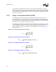
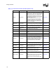
Using equations Equation 10-2 through Equation 10-5 a 3-conductor system can be replaced with a
single transmission line model. The odd and even modes will be the worst-case patterns for mode
dependent signal integrity and velocity differences.
The SLEM method has some drawbacks. The SLEM method will only model the impedance and
velocity differences due to crosstalk. Noise coupling due to excessive coupling is not modeled.
However, experience indicates that the impedance and velocity differences are the dominant effect
of crosstalk in a system. After the SLEM model is used to determine the initial solution space and
the majority of the simulations have been completed, it is necessary to perform a small number of
fully coupled simulations to catch any timing impacts due to effects not captured by the SLEM
model.
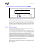
10.3.2 Serpentine Traces
A serpentine net is a transmission line that is routed in such a manner so that sections of the net
double back and couple to another segment of the same net.
A serpentine transmission line is sometimes necessary in order to properly match lengths between
nets. It is important to properly control the serpentine in order to avoid signal integrity and timing
problems. The primary impact of a serpentine trace is an observed decrease in the flight time when
compared to a straight trace of equal length. This decrease in the flight time is a result of the
crosstalk between parallel sections of the serpentine net. As the signal travels down the
transmission line, a component of the signal will follow the transmission line and behave as though
it were a straight line with no serpentine. However, another portion of the energy will propagate
perpendicular to the parallel routed portions of the serpentine net via the mutual capacitance and
mutual inductance. This creates an extra mode that will arrive at the receiver significantly earlier
than the other component of the signal. If the coupling between parallel sections is high, this will
cause significant timing skew when attempting to match traces length on a bus. Furthermore, if the
coupling very high, significant signal integrity problems can result.
The serpentine guidelines included in this document were based on HSPICE simulations with
different spacing between parallel sections. The guidelines were chosen to significantly limit the
effect of serpentine net.
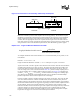
Figure 10-5. Cross-Section of a 3-Conductor System Used to Create a SLEM Model
A B C
FR4
Even mode =
A B C
Odd mode =
A B C