
Intel Xeon Processor and Intel E7500/E7501Chipset Compatible Platform Design Guide
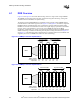

Memory Interface Routing Guidelines
88 Intel
®
Xeon™ Processor and Intel
®
E7500/E7501 Chipset Compatible Platform Design Guide
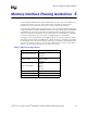
NOTES:
1. On a compatible motherboard, use a 6.2 Ω for an E7500 chipset MCH and a 0 Ω for an E7501 chipset MCH.
On a motherboard which only supports an E7501 chipset MCH, no Rs is required. Instead, change the
impedance at the first DIMM pin.
2. On a compatible motherboard, use a 33.2
Ω for an E7500 chipset MCH and a 39.2 Ω for an E7501 chipset
MCH.
3. The DQS pair in the group must also be tuned to each other with this parameter. The DQ and DQS lines in
the same group must be length tuned to all DIMMs. Tune all lengths to the E7501 chipset MCH package
trace lengths.
4. The MCH to DIMM1 trace length is defined as E7501 chipset MCH die pad (PCB trace velocity equivalent,
see Section 12.5) to DIMM1 pin.
5. Within the same group, this length range should not vary by more than 50 mils. However, the length can be
anywhere from 1.0” to 1.2”.
NOTE: Indicated lengths measure from the MCH die pad (PCB trace velocity equivalent, see Section 12.5) to
the DIMM connector pin (including the series resistor).
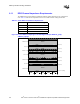
Table 6-4. Source Synchronous Signal Group Routing Guidelines
Parameter 3-DIMM Solution 4-DIMM Solution Reference
Signal Group DQ[63:0], CB[7:0], DQS[17:0]
Topology Daisy Chain Figure 6-6
Reference Plane Ground Figure 6-5
MCH to Rs Trace Impedance (Z
0
)50 Ω ± 10% 45 Ω ± 10% Table 6-2
Rs to Rtt Trace Impedance (Z
0
)50 Ω ± 10% 55 Ω ± 10% Table 6-2
MCH to Rs Trace Width 5 mil 6 mil Figure 6-5
Rs to Rtt Trace Width 5 mil 4 mil Figure 6-5
Nominal Trace Spacing 15 ± 1 mil 15 ± 1 mil Figure 6-5
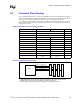
MCH to DIMM1 Trace Length
4
3.5" to 6.3" 6.1” to 6.3”
Figure 6-6
Rs to DIMM1 Trace Length 0.1" to 0.8" 0.1" to 0.8" Figure 6-6
DIMM to DIMM Trace Length 1.0" to 1.2” ± 50 mil
5
1.0" to 1.2” ± 50 mil
5
Figure 6-6
DIMM to Rtt Trace Length < 0.8” 0.3" to 1.3” Figure 6-6
Series Resistor (Rs) 10
Ω ± 2% 0 Ω /6.2 Ω ± 5%
1
Figure 6-6
Termination Resistor (Rtt) 39.2
Ω ± 1% / 33.2 Ω ± 1%
2
34.8 Ω ± 1% Figure 6-6
MCH Breakout Guidelines 5/5, < 500 mil 5/5, < 500 mil
Length Tuning Requirements DQ to DQS: ± 25 mil
3
DQ to DQS: ± 25 mil
3
Section 12.5
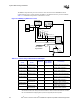
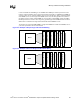
Figure 6-6. Source Synchronous Topology
DIMMs
DQ/CB Data Group
Associated DQS
DQ/CB Data Group
Associated DQS
MCH
DIMM to
DIMM
DDR VTERM
(1.25 V)
MCH to DIMM1
Rs
Rs
Rs
Rs
Rtt
Rtt
Rtt
Rtt
Rs to
DIMM1
DIMM to
DIMM
DIMM to
DIMM
DIMM
to Rtt