
Intel Xeon Processor and Intel E7500/E7501Chipset Compatible Platform Design Guide

Platform Clock Routing Guidelines
54 Intel
®
Xeon™ Processor and Intel
®
E7500/E7501 Chipset Compatible Platform Design Guide
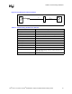
NOTES:
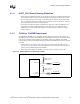
1. All lengths must be matched within 100 mils of target length.
2. 66 MHz clock lines routed with 25-mils isolation from any other signal.
3. Length from CK408B to MCH must be between 3 inches and 9.5 inches.
4. Each connector is equivalent to ~ 0.60 inch of trace.
5. Z is the card trace length.
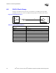
NOTES:
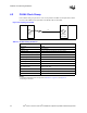
1. All lengths must be matched within 100 mils of target length.
2. 66 MHz clock lines routed with 25-mils isolation from any other signal.
3. Length from CK408B to MCH must be between 3 inches and 9.5 inches.
4. Each connector is equivalent to ~ 0.60 inch of trace.
5. Z is the card trace length.
6. Each riser is equivalent to ~0.60 + Y where Y is the riser card trace length.
7. The riser must be built with the CLK66 trace length matched to the motherboard routed length.
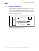
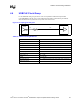
Figure 4-8. Example of Adding a Single Connector
Total Length = X
43 Ω
MCH
Intel
®
P64H2
43 Ω
Z
Motherboard Trace Length
= X - 0.34" - 0.60" - Z
= X - 0.94" - Z
Resistor must be within
500 mils of CK408B
CK408B
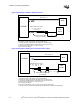
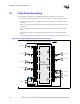
Figure 4-9. Example of Adding Two Connectors and/or a Riser
Total Length = X
Connector
CK408B
MCH
Intel
®
P64H2
43 Ω
43 Ω
YZ
Motherboard Trace Length
= X - 0.34" - 0.60" - Z - 0.60" - Y
= X - 1.54" - Z - Y
Resistor must be within 500
mils of CK408B