
Intel Xeon Processor and Intel E7500/E7501Chipset Compatible Platform Design Guide


Intel
®
Xeon™ Processor and Intel
®
E7500/E7501 Chipset Compatible Platform Design Guide 255
Layout Checklist
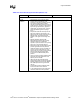
General
Guidelines, cont.
• Keep the total length of each differential pair
under 4".
• Issues found with traces longer
than 4":
– IEEE phy conformance
failures
– excessive EMI and or
degraded receive BER.
• Do not route the transmit differential traces
closer than 100 mils to the receive
differential traces.
• To minimize crosstalk.
• Distance between differential traces and any
other signal line must be at least 100 mils.
(300 mils recommended).
• To minimize crosstalk.
• Route 5 mils on 7 mils for differential pairs
(out of LAN phy).
• To meet timing and signal quality
requirements.
• Differential trace impedance should be
controlled to be ~100
Ω.
• To meet timing and signal quality
requirements.
• For high-speed signals, the number of
corners and vias should be kept to a
minimum. If a 90-degree bend is required,
use two 45-degree bends.
• To meet timing and signal quality
requirements.
• Traces should be routed away from board
edges by a distance greater than the trace
height above the ground plane.
• This allows the field around the
trace to couple more easily to the
ground plane rather than to
adjacent wires or boards.
• Do not route traces and vias under crystals
or oscillators.
• This prevents coupling to or from
the clock.
• Trace width to height ratio above the ground
plane should be between 1:1 and 3:1.
• To control trace EMI radiation.
• Traces between decoupling and I/O filter
capacitors should be as short and wide as
practical.
• Long and thin lines are more
inductive and would reduce the
intended effect of decoupling
capacitors.
• Vias to decoupling capacitors should be
sufficiently large in diameter.
• To decrease series inductance.
• Isolate I/O signals from high speed signals. • To minimize crosstalk.
• Avoid routing high-speed LAN or Phone line
traces near other high-frequency signals
associated with a video controller, cache
controller, processor, or other similar device.
• To minimize crosstalk.
• Place the 82562ET/EM part more than 1.5"
away from any board edge.
• This minimizes the potential for
EMI radiation problems.
• Place at least one bulk capacitor (4.7 µF or
greater OK) on each side of the Intel
®
82562ET/EM.
• Research and development has
shown that this is a robust design
recommendation.
• Place decoupling capacitors (0.1 µF) as
close to the 82562ET/EM as possible.
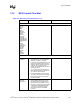
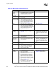
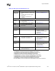
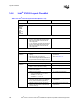
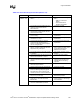
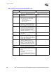
Table 14-4. Intel
®
ICH3-S Layout Checklist (Sheet 2 of 4)
Checklist Items Recommendations Comments