
Intel Xeon Processor and Intel E7500/E7501Chipset Compatible Platform Design Guide


Platform Power Delivery Guidelines
180 Intel
®
Xeon™ Processor and Intel
®
E7500/E7501 Chipset Compatible Platform Design Guide
11.2.4 VR Module 9.1 Recommendations
Intel has defined VRM 9.1 for supplying VCC_CPU power to Intel Xeon processor based systems.
The VRM 9.1 definition includes Remote-Sense, Current Share, and Output Enable features.
VRM 9.1 suppliers must provide these features and must meet voltage and current requirements set
forth in the VRM 9.1 DC-DC Converter Design Guidelines.
The VRM 9.1 Module, which provides VCC_CPU supply to the Intel Xeon processor, has the
capability of supplying a broad range of voltages (+1.1 V to +1.85 V).
It is highly desirable in DP applications that a current-sharing capability be available. The
VRM 9.1 covers the specification for supporting this feature. A VRM 9.1 designed for current
sharing must be capable of continuously producing a current that is higher than the rated value by a
factor of half of the current sharing accuracy. For example, if a particular VRM 9.1 is designed to
supply a 50 A processor as a maximum with 10% accuracy, the difference between the output
currents of two or more VRM 9.1s in parallel may be as much as 5 A at any value of current
actually produced, even to the point where one VRM 9.1 is producing 5 A, and one in parallel with
it is producing no current in supplying a 5 A load. This is necessary to insure that the higher-current
VRM 9.1 in a current-sharing pair does not operate above its limits due to current sharing errors.
One pin of the VRM 9.1 is reserved for current sharing control for a VRM 9.1 designed for star-
point or single-wire current sharing (i.e., Ishare). This pin will be connected to other VRM 9.1s
within the system.
The VRM 9.1 output slew rate is specified at 50 A/µs. The slew rate for the Intel Xeon processor is
450 A/µs at the socket pins. The system designer must provide adequate bulk and high-frequency
decoupling on the motherboard to meet the appropriate processor required slew rate.
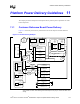
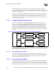
Figure 11-5 shows the recommended VRM implementation referred to as the “row” pattern since
the VRM and processor sockets are placed in a row with one another. The advantages of this
placement is that the VRM current flow to its adjacent processor socket is not restricted by the
other VRM.