
Intel Xeon Processor and Intel E7500/E7501Chipset Compatible Platform Design Guide

Intel
®
Xeon™ Processor and Intel
®
E7500/E7501 Chipset Compatible Platform Design Guide 121
Intel
®
82870P2 (P64H2)
8.1.7 Loop Clock Configuration
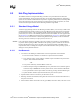
You must tie PxPCLKO6 to PxPCLKI because this clock always runs and is needed by the internal
PCI PLLs to properly align output signals with the external clocks by removing clock insertion
delay. The PxPCLKO6 signal does not have to be routed through a bus switch before returning to
PxPCLKI.
NOTE: L
fbi
must be the same length (± 25 mils) as any device clock length on the same bus. If a device is down
on the motherboard, L
fbi
= L2. If a devices is on an expansion card, L
fbi
= L2 + 2.5 inches. Refer to
Figure 8-9 for L2 and Figure 8-10 for L
fbi
.
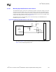
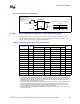
Figure 8-10. Loop Clock Topology
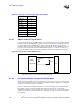
Table 8-13. Loop Clock Configuration Routing Length Parameters
Clock Speed / Configuration L
fbo
(inches) L
fbi
(inches)
33 MHz / No HP 3.5 – 5.5 2.9 – 7.9
66 MHz / No HP 4.5 – 5.5 3.9 – 4.9
66 MHz / With HP 0.25 – 1.0 7.0 – 12.0
100 MHz / No HP
≤ 1.0 See Note
100 MHz / With HP 4.5 – 5.5 3.9 – 4.9
133 MHz / No HP 0.25 – 1.0 See Note
133 MHz / With HP 3.5 – 4.0 5.5 – 5.7
Intel
®
P64H2
33 Ω
PxPCLKO6
PxPCLKI
L
fbi
L
fbo