
Intel Xeon Processor Multiprocessor Platform Design Guide

93
Methodology for Determining Topology and Routing Guidelines
9.1.1.1 Setup Time
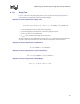
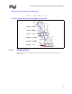
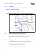
Figure 9-2 shows the setup timing diagram for a source synchronous bus design. Equation 9-1
gives the total loop equation derived from the timing diagram.
Equation 9-1. Source Synchronous Setup Time
• T
co
(strobe)[(data)] is the driver delay of the strobe [data]
• T
flight
(strobe)[(data)] is the flight time of the strobe [data] interconnect
• T
setup
is the receiver's setup requirement
• T
margin
is the available timing margin for the setup time
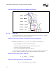
The loop equation can be simplified and solved for T
margin_setup
. The equation can be broken into
two parts, valid before and interconnect skew. Then, the setup margin can be determined.
Equation 9-2. Source Synchronous, Valid Before
Equation 9-3. Source Synchronous, Interconnect Skew
Equation 9-4. Source Synchronous Setup Margin
setupflightco
TstrobeTstrobeT −+ )()( )(
_arg
dataTT
cosetupinm
−− 0)( =− dataT
flight
minmax
)()( strobeTdataTT
cocovb
−=
minmaxmax,
)()( strobeTdataTT
flightflightskew
−=
setupskewvbsetupinm
TTTT −−−=
max,min,_arg