
Intel Xeon Processor Multiprocessor Platform Design Guide

71
Processor Power Distribution Guidelines
8.9 Decoupling Capacitors
8.9.1 Decoupling Technology and Transient Response
The inductance of the system due to cables and power planes slows the power supply's ability to
respond quickly to a current transient. Decoupling a power plane can be broken into several
independent parts. The closer to the load the capacitor is placed, the more inductance that is
bypassed. By bypassing the inductance of leads, power planes, etc., less capacitance is required.
However, closer to the load there is less room for capacitance. Therefore trade-offs must be made.
Intel Xeon processors MP cause very large switching transients. These sharp surges of current
occur at the transition between low power mode and high power mode. It is the responsibility of the
system designer to provide adequate high-frequency decoupling to manage the highest frequency
components of the current transients. To lower total board inductance and resistance, Intel Xeon
processors MP are designed with approximately 141 V
CC
and 141 V
SS
(ground) pins. Intel Xeon
processors MP with up to 2-MB L3 cache on the 0.13 micron process are designed with 188 V
CC
and 189 V
SS
(ground) pins. The designer needs to support a current slew rate of 450 A/µs at the
socket pins. Larger bulk storage such as OSCON capacitors, supply current during longer lasting
changes in current demand by the component, such as coming out of an idle condition. Similarly,
they act as a storage well for current when entering an idle condition from a running condition.
All of this power bypassing is required due to the relatively slow speed at which a DC-to-DC
converter can react. A typical voltage converter has a reaction time on the order of 1 µs to 10 µs
while the processor's current steps are on the order of 100 ns to 200 ns. Bulk capacitance supplies
energy from the time the high-frequency decoupling capacitors are drained until the power supply
can react to the demand. More correctly, the bulk capacitors in the system slow the transient
requirement seen by the power source to a rate that it is able to supply, while the high-frequency
capacitors slow the transient requirement seen by the bulk capacitors to a rate that they can supply.
A load-change transient occurs when coming out of or entering a low power mode. This load-
change transient can be on the order of 55 Amps. These are not only quick changes in current
demand, but also long lasting average current requirements. This occurs when the processor enters
or leaves a low power state. Please refer to the processor datasheet for more information on the low
power states. Note that even during normal operation, the processor current requirements can
change by as much as 70% (± 10%) of the max current very quickly.
Maintaining voltage tolerance, during these changes in current, requires high-density bulk
capacitors with low Effective Series Resistance (ESR) and low Effective Series Inductance (ESL).
Use thorough analysis when choosing these components.
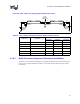
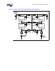
8.9.2 Location of High-Frequency Decoupling
A system designer for Intel Xeon processors MP and Intel Xeon processors MP with up to 2-MB
L3 cache on the 0.13 micron process should properly design for the high-frequency decoupling.
High-frequency decoupling should be placed as close to the power pins of the processor as
physically possible. Use both sides of the board if necessary for placing components in order to
achieve the optimum proximity to the power pins. This is vital as the inductance of the board's
metal plane layers could cancel the usefulness of these low inductance components.
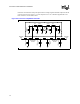
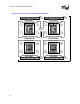
Another method to lower the inductance that should be considered is to shorten the path from the
capacitor pads to the pins that it is decoupling. If possible, place the vias connecting to the planes
within the pad of the capacitor. If this is not possible, keep the traces as short and wide as is