
Intel Xeon Processor Multiprocessor Platform Design Guide


65
Processor Power Distribution Guidelines
8.5 System Design
8.5.1 Multiple Voltages
The voltage regulator modules that provide V
CC
supply to processor and have the capability of
supplying voltages from +1.1 V to +1.85 V. The V
CCA
supplies power to the processor core and
on-die termination used for AGTL+ bus.
Multiple voltages required for Intel Xeon processor MP based systems are V
CC_MAX
= 1.7 V and
SM_V
CC
= 3.3 V. Similarly, for and Intel Xeon processor MP with up to 2-MB L3 cache on the
0.13 micron process processors V
CC_MAX
= 1.475 V and SM_V
CC
= 3.3 V. V
CCIOPLL
, V
CCA
, and
V
SSA
are the power supplies to the internal PLL. V
CCIOPLL
, V
CCA
and V
SSA
must be connected to
V
CC
through a discrete RLC filter as described in Section 8.13. Refer to the processor datasheet for
the pin location of these voltage supplies and specifications for all processor voltage supplies.
8.5.2 Voltage Sequencing
When designing a system with multiple voltages, there is always the issue of ensuring that no
damage occurs to the system during voltage sequencing. Voltage sequencing is the timing
relationship between two or more voltages, such as V
CC
and SM_V
CC
. Sequencing applies to the
power voltage levels and the levels of certain other crucial signals when the user turns on or off the
power supply, or the system enters a failure condition. V
CC
from the voltage regulators should be
enabled after assertion of the Power Supply Power Good signal and disabled upon de-assertion of
the Power Supply Power Good signal. In addition, in the event of any processor asserting its
THERMTRIP# signal, V
CC
must be disabled within 0.5 s. Please contact the chipset vendor for the
recommended circuit to disable power to the processor.
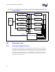
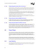
8.5.3 Block Diagrams with Voltage Regulator Modules
Figure 8-1 depicts the recommended four-way baseboard solutions involving local voltage
regulator modules (VRMs). The block diagrams also recommend the implementation of logic for
monitoring the VID [4:0] of all processors. This logic should determine that all of the installed
processors are requesting the same V
CC
. If mixed voltage processors are detected the output enable
signal (OUTEN) of all voltage regulators must be disabled. Note that if a processor is not installed
the VID [4:0] of that processor are high, and this should not cause disabling of the output of other
VRMs.