
Intel Xeon Processor Multiprocessor Platform Design Guide

39
System Bus Routing
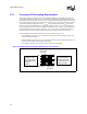
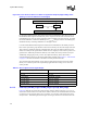
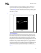
distance from the package pin of one agent to the package pin of the next should be between
3.0 inches and 6.1 inches. There is an “island” of failing solution space based on L1 and L2
lengths. Refer to Figure 6-6 for a diagram of acceptable routing lengths.
The island in Figure 6-6 represents a configuration where the ringback on the system bus violates
specification. This ringback is also a factor of ISI buildup over multiple cycles. This ringback is
highly dependent on the length of L1 versus the length of L2. Use the diagram to find acceptable
routing lengths for L1 and L2.
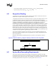
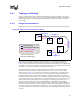
Trace Length Balancing
Length must be added to the motherboard trace between each agent to compensate for package
length differences that exist within a source synchronous data group. This length compensation
will result in minimizing the source synchronous skew that exists on the system bus. Without the
length compensation the flight times between a data signal and its strobe will be different, which
results in an inequity between the setup and hold times. Since the strobe has a shorter package
length there will be favoritism toward hold time and thus, length compensation is necessary to meet
the setup time requirement. Note this will not make the pad-to-pad lengths between all agents equal
in length, but it will balance the strobe-to-signal skew in the middle of the setup and hold window
between all driver-receiver combinations. The delta between a signal's processor package length
(cpu_pkglen) and the longest signal's processor package length (max_cpu_pkglen) in that source
synchronous group must be added to the motherboard trace between each agent. The following
equations provide a guideline for trace length balancing. Simulation results should provide a more
accurate assessment of what these compensation lengths should be for a specific design. See
Equation 6-1. This compensation length is added to each of lengths L1, L2, L3, and L4 as shown in
Figure 6-4.
Figure 6-6. L1 vs. L2 Length Dependencies
3
3.3
3.6
3.9
4.2
4.5
4.8
5.1
5.4
5.7
6
3
3.2
3.4
3.6
3.8
4
4.2
4.4
4.6
4.8
5
5.2
5.4
5.6
5.8
6
L1 (inches)
L2 (inches)
L1 and L2 vs. Low Ringback (L3 and L4 Held Constant to 4")