
Intel Xeon Processor and Intel E7500/E7501Chipset Compatible Platform Design Guide

Intel
®
Xeon™ Processor and Intel
®
E7500/E7501 Chipset Compatible Platform Design Guide 241
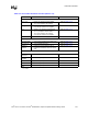
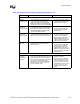
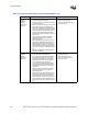
Schematic Checklist
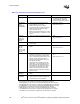
Power Decoupling Requirements
VCC (1.8 V) • Eight 0.1 µF capacitors near the P64H2.
• Two 4.0 µF capacitors near regulator.
• Refer to Section 11.5.2.
VCC1_8 • Two 1.0 µF capacitors near the P64H2.
• One 100.0 µF capacitors near regulator.
• Refer to Section 11.5.2.
3.3 V • Twenty 0.1 µF capacitors near the P64H2.
• Six 1.0 µF capacitors near the P64H2.
•Two
4.0 µF capacitors near regulator.
• One 100.0 µF capacitors near regulator.
• Refer to Section 11.5.2.
VCC5REF • Connect to 5 V Power Supply. • 5 V.
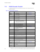
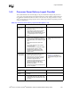
Power Sequencing Requirements
1.8 V and CLK66 • 1.8 V must be valid before first CLK66 pulse. • Refer to Section 11.5.4.
1.8 V and 3.3 V • 1.8 V must drop before 3.3 V. • Refer to Section 11.5.4.
PWRGD to
PCIRST#
• PCIRST# must lag PWRGD by 100 ms.
• PCIRST# must deassert with 60 ns of MCH
reset.
• Refer to Section 11.5.3
Miscellaneous Signals
BPCLK100
BPCLK133
• These can be left as no connects.
CLK200
CLK200#
• 8.2 k
Ω ± 5% pull-up to 3.3 V.
TP0 • 8.2 k
Ω ± 5% pull-up to 3.3 V.
TEST# • 8.2 k
Ω ± 5% pull-up to 3.3 V.
RASERR# • 8.2 k
Ω ± 5% pull-up to 3.3 V.
NOTE:
1. x = A or B
Table 13-4. Intel
®
P64H2 Schematic Checklist (Sheet 4 of 4)
Checklist Items Recommendations Comments