
Intel Xeon Processor and Intel E7500/E7501Chipset Compatible Platform Design Guide

Intel
®
82870P2 (P64H2)
132 Intel
®
Xeon™ Processor and Intel
®
E7500/E7501 Chipset Compatible Platform Design Guide
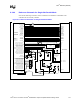
8.2.7 Dual-Slot Parallel Mode
Dual-slot parallel mode is used when it is desirable to have two slots that are Hot-Pluggable. No
serialization/deserialization logic is required for this mode of operation.
8.2.7.1 Required Additional Logic
Dual-slot parallel mode requires a power switch to be used to turn the slot power on and off. Dual-
slot parallel mode also requires the use of a bus and clock switch. Unlike single-slot parallel mode,
the PCI signals are not driven to ground when a PCI card is to be disconnected. In addition, dual-
slot parallel mode requires auto bus and clock disable logic to immediately disable the PCI bus and
clock when the power fault signal (from the power switch) goes active.
If the platform supports PME# or SMBus connections to the slots, isolation logic is required to
disconnect these signals before inserting or removing a card. See PCI Hot-Plug Specification,
Revision 1.1 for implementation details.
8.2.7.2 Debounced Hot-Plug Switch Input
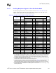
The switch inputs (PAIRQ15 and PAIRQ10 in this case—see Table 8-19) to the Hot-Plug
controller do not require debouncing logic in this mode. This logic is contained within the P64H2.
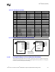
8.2.7.3 Comparator Circuit for PCIXCAP1/PCIXCAP2 Pins
A comparator circuit is required for properly decoding the PCI/PCI-X capability of the slot. Refer
to the PCI Local Bus Specification, Revision 2.2 for this circuit. An example of this circuit is also
contained in the reference schematics. For a frequency reference matrix, see Table 8-16.
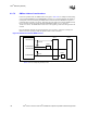
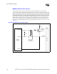
8.2.7.4 Tri-State Buffer or 2:1 Multiplexer for HPx_SLOT [2:0]
As with single-slot parallel mode, the HPx_SLOT [2:0] pins are pull-ups/pull downs for
determining the slot count and mode of operation for the P64H2 Hot-Plug controller in dual-slot
parallel mode. The strapping value on these pins is latched on the rising edge of PWROK. In dual-
slot parallel mode these pins also function as the PCIXCAP1A, PCIXCAP2A, and PCIXCAP1B
inputs to the controller. Logic must exist to preserve the slot count value when the system is in reset
(PWROK signal is low). Connecting a tri-state buffer or a 2:1 multiplexer to these pins to pull the
line high or low accordingly can do this. The PWROK signal can be used to enable the tri-state
buffer to drive the line high or low or select the multiplexed signal. See Figure 8-14 for a tri-state
buffer example circuit, and Figure 8-15 for a 2:1 multiplexer circuit example.
8.2.7.5 HPx_SID Output Signal
In dual-slot parallel mode, this signal is connected to the Amber LED slot status indicator. During a
reset operation, this signal goes high which could flicker the LED on and confuse the user. To
avoid having this LED turn on during a reset operation (PWROK logic zero), it is possible to use a
buffer to electrically isolate this LED from the HPx_SID signal. The PWROK input signal to the
P64H2 should be used to enable this buffer. See the dual-slot parallel mode reference schematic in
Section 8.2.7.9 for an example of this circuit.
8.2.7.6 Pull-Ups/Pull-Downs in Dual-Slot Parallel Mode
All PCI signals should follow the PCI Local Bus Specification, Revision 2.2 pull-up requirements
whether they are multiplexed or not. Any unused input signals should be pulled to 3.3 V through an
8.2 k
Ω ± 5% resistor to keep them from floating.