
Intel Xeon Processor and Intel E7500/E7501Chipset Compatible Platform Design Guide


Intel
®
82870P2 (P64H2)
118 Intel
®
Xeon™ Processor and Intel
®
E7500/E7501 Chipset Compatible Platform Design Guide
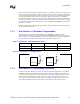
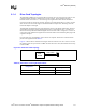
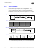
Figure 8-4 shows a PCI-X channel with a device down before a riser card connector. If a one-slot
riser is used, the channel can be run up to PCI-X 100 MHz. If a three-slot riser is used, the channel
can be run up to PCI-X 66 MHz.
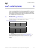
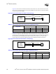
Figure 8-5 shows a riser card topology with a device down after the riser card connector. The
one-slot riser requires a 10 Ω series resistor on the riser between the riser fingers and the connector.
The three-slot riser configuration cannot be run at PCI 66 MHz. It requires a 15 Ω series resistor on
the baseboard between the P64H2 and the Riser connector closer to the riser. A second 15 Ω
resistor is also need on the riser itself between the riser card fingers and the first connector.
Figure 8-4. Device Down before PCI-X Riser Card Topology
Table 8-7. Device Down before PCI-X Riser Card Length Requirements
Configuration
Intel
®
P64H2 to Device Device to Riser
Lower Upper Lower Upper
PCI-X 100 MHz, 1 slot riser 0.0” – 6.0” 0.0” – 5.0” 0.0” – 6.0” 0.0” – 5.0
PCI-X 66 MHz, 3 slot riser 1.0” – 6.0” 1.0” – 4.0” 1.0” – 4.0” 1.0” – 4.0”
Intel
®
P64H2
P64H2 to Device
Device
Ris er
Device to Riser
Figure 8-5. Device Down after PCI-X Riser Card Topology
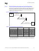
Table 8-8. Device Down after PCI-X Riser Card Length Requirements
Configuration
Intel
®
P64H2 to Riser Riser to Device
Lower Upper Lower Upper
PCI-X 100 MHz, 1 slot riser 0.0” – 8.0” 0.0” – 8.0” 0.0” – 8.0” 0.0” – 8.0”
PCI-X 66 MHz, 3 slot riser 1.0” – 6.0” 1.0”– 4.0” 1.0” – 4.0” 1.0” – 2.25”
Intel
®
P64H2
P64H2 to Riser
Device
Ris er
Ris er to Dev ic e