
ITP700 Debug Port Design Guide


R
ITP700 Debug Port Design Guide 41
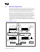
3.5 Mechanical Requirements
The ITP debug port adapter (DPA) plugs into the target system’s onboard debug port connector.
The ITP cable connects the DPA hardware to the ITP hardware located on a host system. The host
system runs the ITP software. In order for the ITP cabling to egress the system under test, an
aperture of two inches minimum width by one-inch minimum height must be available. Please
contact your run-control tool vendor for complete mechanical constraints for other tools.
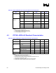
Examples of connectors that will fulfill the requirements of a debug port connector would be either
the Framatome Connectors International* (FCI*) #61641-303 which is a 25 pin through-hole
mount header or the FCI* #61698-302TR which is a 25 pin surface mount header. The surface
mount version is recommended for its compatibility with a new feature on the DPA. This feature
provides improved retention of the DPA to the header and is particularly useful on boards that may
be oriented vertically or where the DPA is located on the bottom side of the board. Full
specifications for these connectors, including PCB layout guidelines, are available from an FCI
sales representative. Please note that changes in the keepout volume have been made in order to
accommodate the new retention feature of the ITP. All dimensions in the following diagrams are in
units of inches.
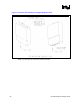
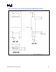
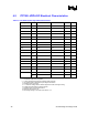
Figure 10. Debug Port Connectors
<0.159>
Pin 2
Pin 1
Pin 26
Removed
Pin 2
Pin 1
<0.159>
<1.024>
Top view of through-hole
connector as assembled to target
ITP M ating
Surface
Target PCB
Mating
Surface
Front View
Front View
Side View
Target PCB
Mating
Surface
ITP Mating
Surface
<0.059>
<0.098>
<1.024>
N
ot To Scale
Pin 26
Removed
Top view of surface connector as
assembled to target